Lead frame, semiconductor device, method of manufacturing the lead frame, and method of manufacturing the semiconductor device

a technology of lead frame and lead frame, which is applied in the direction of electrical apparatus construction details, casings/cabinets/drawers, casings/cabinets/drawers details, etc., can solve the problems of disadvantageous deformation, short circuit, and reduced width and pitch, so as to suppress short circuit, improve productivity, and reduce resin molding conditions

Active Publication Date: 2011-10-18
TESSERA ADVANCED TECH
View PDF10 Cites 0 Cited by
  • Summary
  • Abstract
  • Description
  • Claims
  • Application Information

AI Technical Summary

Benefits of technology

[0041]According to the preferred embodiments of the present invention, it is possible to achieve a reliable semiconductor device which can suppress a short circuit of a wire to an adjacent lead, the short circuit being caused by wire sweep during the injection of molding resin.
[0043]Further, in recent years, lead frames with multiple rows have been used to improve productivity. However, when using lead frames having multiple rows, molten resin injected out of a pot passes through a runner and flows into the cavities (dies for respective packages) of the rows, causing variations in time periods from when injection is started to when the cavities are filled with the resin. For this reason, when using a lead frame having multiple rows in the prior art, the resin molding conditions are further restricted.
[0044]On the other hand, the preferred embodiments of the present invention can structurally suppress a short circuit caused by wire sweep. Thus it is possible to relax the conditions in a resin molding step, reduce a resin injection time and a curing time with molding resin having a short curing time, and increase the number of rows in the lead frame. Consequently, the preferred embodiments of the present invention can improve the productivity of the semiconductor device. The lead frame, the semiconductor device, and the method of manufacturing the lead frame according to the present invention are useful for the stable production of the semiconductor device.
[0045]As has been discussed, the lead frame, the semiconductor device, and the method of manufacturing the lead frame according to the present invention can prevent a short circuit between a wire and the end of an adjacent lead caused by wire sweep during the injection of molding resin, and thus the present invention is useful for the production of a QFP package and so on using a lead frame.

Problems solved by technology

Thus also in lead frames, leads have been reduced in width and pitch, so that the leads are disadvantageously deformed.
When the wires are considerably deformed, a short circuit may occur.
This problem is evident particularly in a semiconductor device using a lead frame having multiple pins and leads with a small pitch.

Method used


Image

  • Lead frame, semiconductor device, method of manufacturing the lead frame, and method of manufacturing the semiconductor device
  • Lead frame, semiconductor device, method of manufacturing the lead frame, and method of manufacturing the semiconductor device
  • Lead frame, semiconductor device, method of manufacturing the lead frame, and method of manufacturing the semiconductor device

Examples


first embodiment

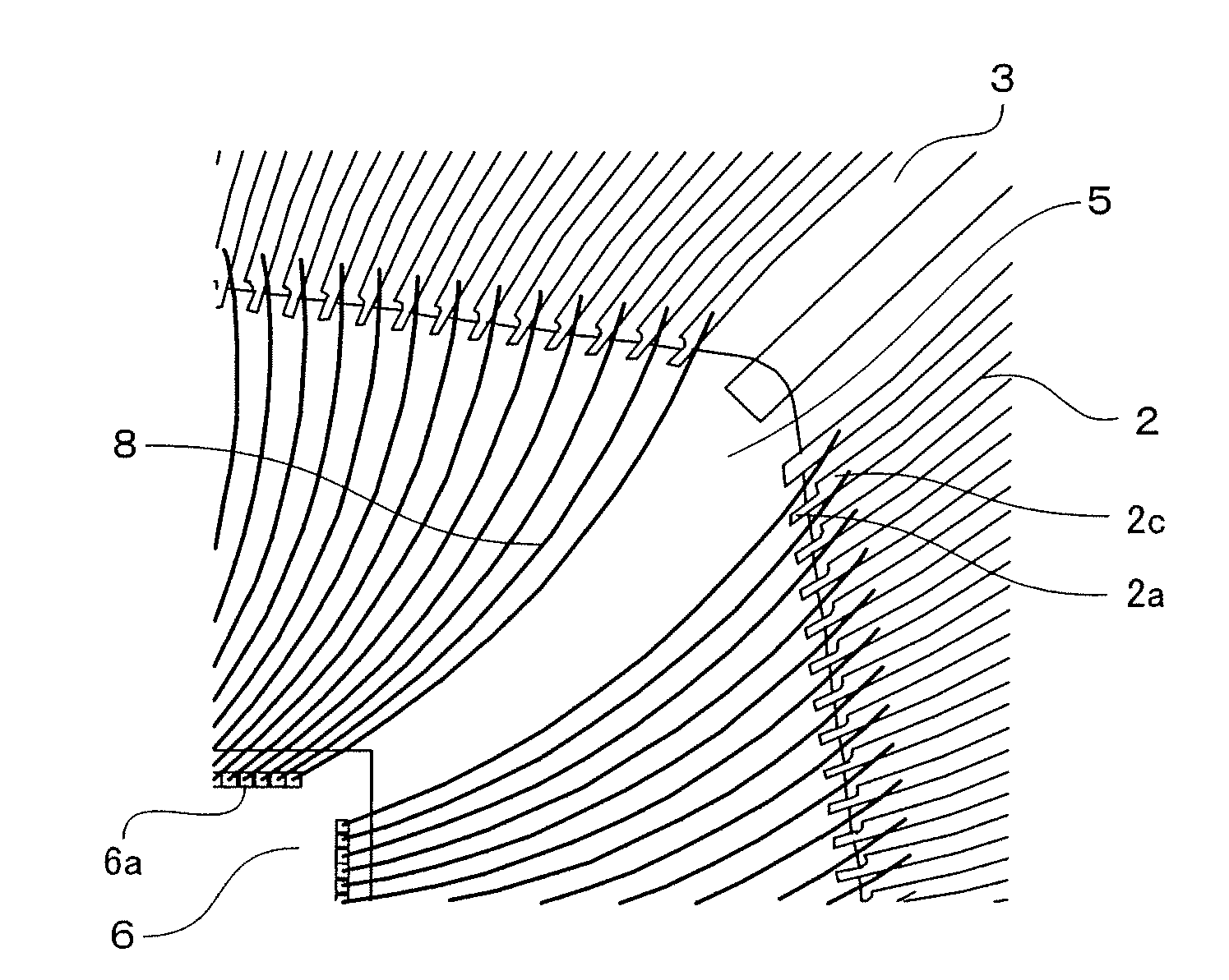
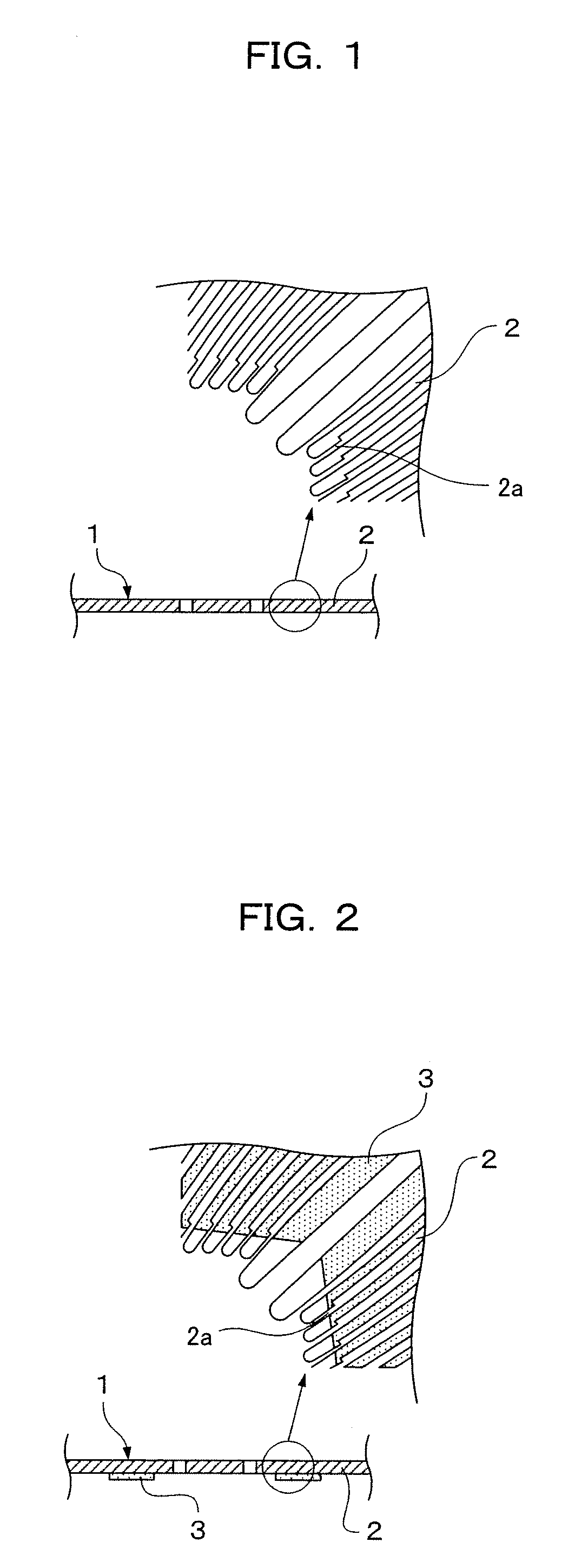
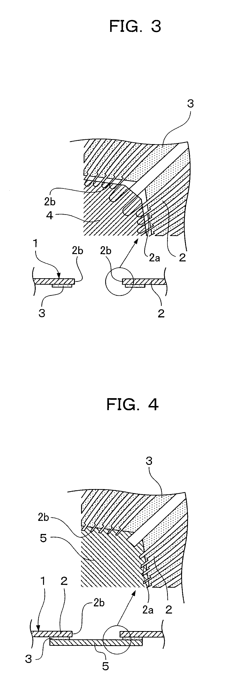
[0069]FIGS. 1 to 4 are main part plan views and process sectional views for explaining the manufacturing process of a semiconductor device according to a first embodiment of the present invention. FIGS. 5 to 7 are process sectional views for explaining the manufacturing process of the semiconductor device according to the first embodiment of the present invention. FIG. 8 is an internal plan view showing the internal configuration of the resin-molded semiconductor device according to the first embodiment of the present invention. FIG. 9 is an enlarged view showing the main part of FIG. 8.

[0070]Referring to FIGS. 1 to 7, the following will describe the manufacturing process of the semiconductor device according to the first embodiment of the present invention.

[0071]First, as shown in FIG. 1, a metal plate is worked by etching or stamping to integrally form a frame (not shown) and a plurality of leads 2 which are connected to the frame and protrude to the center of the frame.

[0072]At t...

second embodiment

[0090]FIG. 10 is a plan view showing a step of cutting the ends of leads and forming a die pad in the manufacturing process of a lead frame according to a second embodiment of the present invention. FIG. 11 is a plan view showing the lead frame according to the second embodiment of the present invention. FIG. 12 is an enlarged view showing the main part of FIG. 11. Members corresponding to the members illustrated in the first embodiment are indicated by the same reference numerals and the explanation thereof is omitted.

[0091]The second embodiment is different from the first embodiment in that the lead frame includes a die pad 14 serving as a support plate disposed in a frame 19.

[0092]In the manufacturing process of the lead frame according to the second embodiment, a metal plate is first worked to integrally form the frame 19, a plurality of leads 2 which are connected to the frame 19 and protrude to the center of the frame 19, and die pad supports 15 connected to the frame 19. At t...


PUM

PropertyMeasurementUnit
angleaaaaaaaaaa
forming anglesaaaaaaaaaa
anglesaaaaaaaaaa

Abstract

A lead frame is provided which can prevent a short circuit between wires and the ends of adjacent leads, the short circuit being caused by wire sweep during the injection of molding resin, in a configuration where the electrodes of a semiconductor chip and the leads disposed around the semiconductor chip. The lead having sides substantially perpendicular to the direction of a resin flow has an end whose upstream side relative to the resin flow is constricted.

Description

FIELD OF THE INVENTION[0001]The present invention relates to a lead frame, a semiconductor device using the same, a method of manufacturing the lead frame, and a method of manufacturing the semiconductor device.BACKGROUND OF THE INVENTION[0002]In recent years, quad flat packages (hereinafter, will be referred to as QFPs) have been widely used as one form of semiconductor devices using lead frames. FIG. 13 is a sectional view of a typical QFP semiconductor device of the prior art.[0003]As shown in FIG. 13, in the QFP semiconductor device, a semiconductor chip 6 having an IC formed thereon is fixed on the top surface of a die pad 14 with an adhesive 7. Further, a plurality of electrodes (not shown) formed on a surface of the semiconductor chip 6 are connected, via a plurality of wires 8, to a plurality of leads 2 radially disposed around the die pad 14. The semiconductor chip 6, the die pad 14, the wires 8, and the joints of the leads 2 and the wires 8 are integrally molded with a mol...

Claims


Application Information

Patent Timeline
Patent Type & Authority Patents(United States)
IPC IPC(8): H01L23/495
CPCH01L21/565H01L2224/32245H01L2224/48247H01L2224/73265H01L2224/48091H01L2224/05554Y10T29/49121H01L2224/92247H01L2924/00012H01L2924/00014H01L24/73H01L2924/14H01L2924/181H01L2924/00
Inventor OGA, AKIRA
Owner TESSERA ADVANCED TECH
Why Eureka
Try Eureka