
Method for detecting digital video interface off-line mode and associated receiver

a digital video interface and receiver technology, applied in the field of digital video interfaces, can solve the problems of increasing costs, high power consumption and heat dissipation, and reducing the overall so as to reduce the power consumption of the digital video interface chip, reduce the total time of mode detection, and reduce the effect of power consumption

Active Publication Date: 2011-10-18
MEDIATEK INC
View PDF11 Cites 7 Cited by
  • Summary
  • Abstract
  • Description
  • Claims
  • Application Information

AI Technical Summary

Benefits of technology

[0009]It is therefore an objective of the claimed invention to provide a method for detecting digital video interface off-line mode and associated TMDS receiver in order to reduce the power consumption of a digital video interface system, and raise system performance.
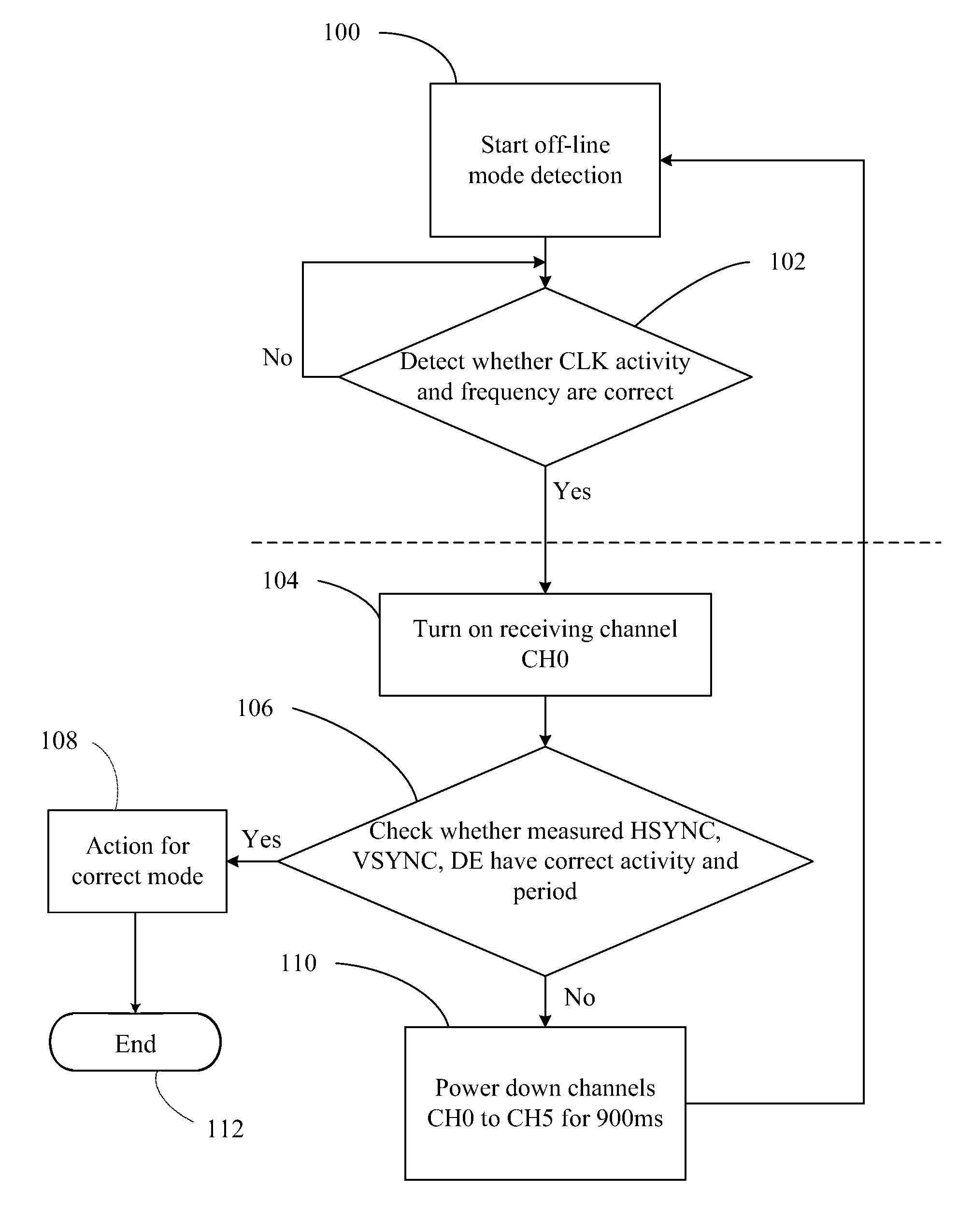
[0011]It is an advantage of the claimed invention that the method for digital video interface off-line mode detection is to reduce the power consumption and failures of a digital video interface system such as a digital video interface chip. The method for digital video interface off-line mode detection of the claimed invention does not need to detect the digital video interface mode all the time but just detecting once in a predetermined period. Hence, the total time of mode detection can be minimized in order to diminish the power consumption of the digital video interface chip.

Problems solved by technology

The requirements of DAC of the video interface and ADC of the liquid crystal display do not only result in increasing the cost but also degradation of the video quality during a plurality of conversions between the analog and digital signals.
The full operation of all channels and the frequent detection of the conventional mode detection circuit causes high power consumption and heat dissipation.

Method used


Image

  • Method for detecting digital video interface off-line mode and associated receiver
  • Method for detecting digital video interface off-line mode and associated receiver
  • Method for detecting digital video interface off-line mode and associated receiver

Examples


Embodiment Construction

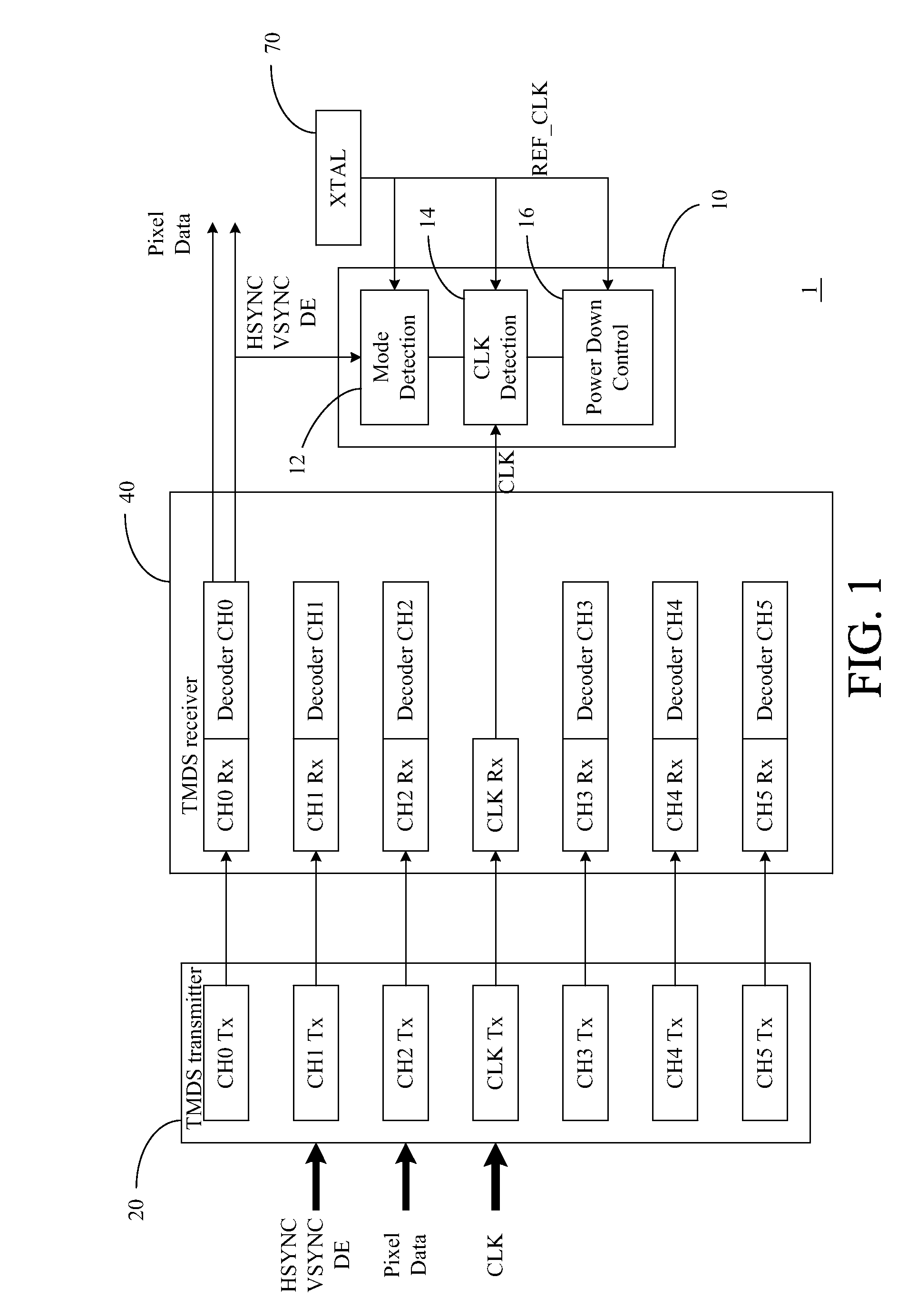
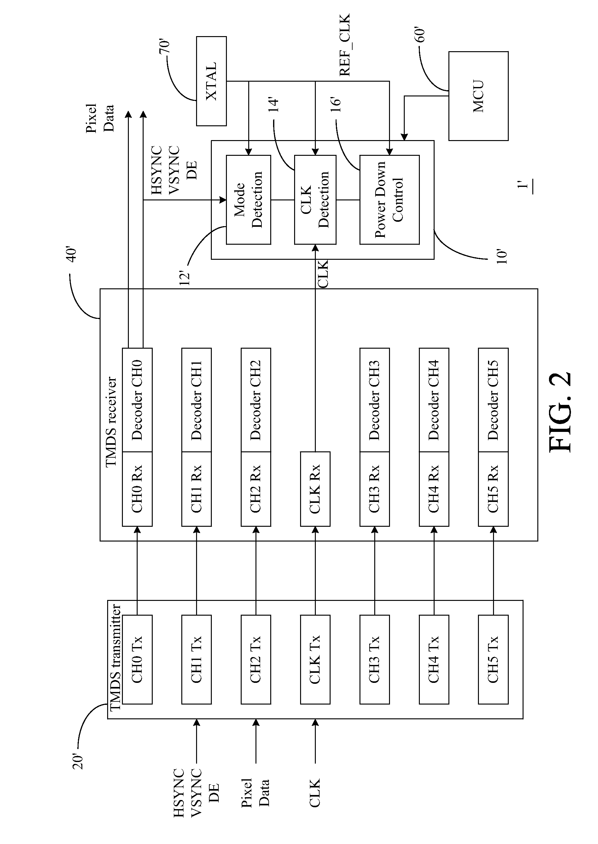
[0017]FIG. 1 shows a block diagram of a digital video interface system 1 including a transmission minimized differential signaling (TMDS) transmitter 20, a TMDS receiver 40, and a crystal oscillator XTAL 70. Meanwhile, the TMDS receiver 40 according to a preferred embodiment of the present invention, receives a plurality of signals, for example, including a horizontal synchronization (HSYNC) signal, a vertical synchronization (VSYNC) signal, a display enable (DE) signal, a clock (CLK) signal and Pixel Data signal, which are transmitted from the TMDS transmitter 20.

[0018]The TMDS transmitter 20 comprises a plurality of encoders and transmitting channels. As shown in FIG. 1, each transmitting channel TX_CHn transmits the signal for channel n, wherein “n” is an integer from 0 to 5, and a transmitting clock channel Tx_CLK transmits a CLK signal to TMDS receiver 40. Meanwhile, the HSYNC, VSYNC, DE, and Pixel Data signals are transmitted by the TMDS transmitter 20.

[0019]On the other side,...


PUM


Abstract

A TMDS receiver includes a plurality of data channels, a clock channel, and an off-line mode detector. Each data channel receives a video signal and the clock channel receives a clock signal. Each data channel comprises a channel decoder for decoding the signals received by the corresponding receiving channel. The off-line mode detector detects an off-line mode detector, and then turns on a plurality of first data channels for a first predetermined period to determine an operation mode of video signal transmitted on said first data channels if the activity of the clock signal is valid. The off-line mode detector also activates a plurality of second data channels among the plurality of data channels according to the operation mode if the operation mode is determined as valid.

Description

CROSS REFERENCE TO RELATED APPLICATION[0001]This is a continuation-in-part of a U.S. patent application Ser. No. 11 / 055,691, filed on Feb. 11, 2005.BACKGROUND OF THE INVENTION[0002]1. Field of the Invention[0003]The present invention relates to digital video interface, and more specifically, to a method for detecting the digital video interface off-line mode and associated receiver.[0004]2. Description of the Prior Art[0005]In general, the cathode ray tube (CRT) display is a stereotype of the analog video display device and the liquid crystal display (LCD) is a stereotype of the digital video display device. Meanwhile, the digital video display device is capable of receiving either analog video signals or digital video signals from a signal source such as a graphic card of the computer but eventually displays digital video signals on the screen.[0006]A called “Digital Visual Interface (DVI)” standard, which has been announced by the Digital Display Working Group (DDWG), spreads a hi...

Claims


Application Information

Patent Timeline
Patent Type & Authority Patents(United States)
IPC IPC(8): G06F3/00H04N5/63
CPCG06F1/3203G06F1/3265Y02B60/1242Y02D10/00
Inventor YANG, CHIA-MINGTSAI, HUIMIN
Owner MEDIATEK INC
Learn More