Vehicle-mounted battery cooling structure

a battery and cooling structure technology, applied in the field of vehicle cooling structures, can solve the problems of reducing cooling efficiency, noise and the like, inevitably sharp bends of the duct, etc., and achieve the effect of efficient exhaustion of cooling air

Active Publication Date: 2011-10-25
TOYOTA JIDOSHA KK +1
View PDF67 Cites 25 Cited by
  • Summary
  • Abstract
  • Description
  • Claims
  • Application Information

AI Technical Summary

Benefits of technology

[0005]The larger the number of sharp bends the duct has, the greater the flow resistance of cooling air, resulting in reduced cooling efficiency, noise and the like. The conventional battery cooling structure requires the duct that guides the cooling air to be bent many times in a limited space, which inevitably causes such problems.
[0006]The present invention was made to solve the above problems. An object of the invention is to provide a vehicle-mounted battery cooling structure which enables efficient exhaustion of cooling air by avoiding a complicated arrangement of the duct connecting a battery and a fan.
[0013]A vehicle-mounted battery cooling structure according to the present invention enables efficient exhaustion of cooling air by avoiding a complicated arrangement of a duct connecting a battery and a fan.

Problems solved by technology

This causes a complicated arrangement of a duct for discharging cooling air and an inevitably sharp bend of the duct.
The larger the number of sharp bends the duct has, the greater the flow resistance of cooling air, resulting in reduced cooling efficiency, noise and the like.
The conventional battery cooling structure requires the duct that guides the cooling air to be bent many times in a limited space, which inevitably causes such problems.

Method used


Image

  • Vehicle-mounted battery cooling structure
  • Vehicle-mounted battery cooling structure
  • Vehicle-mounted battery cooling structure

Examples


first embodiment

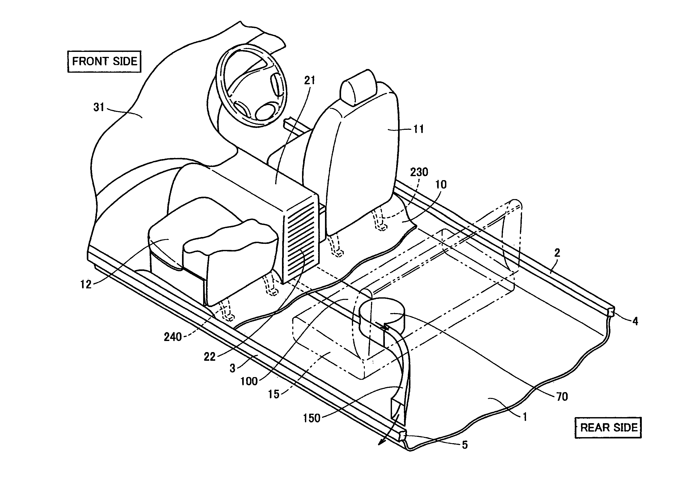
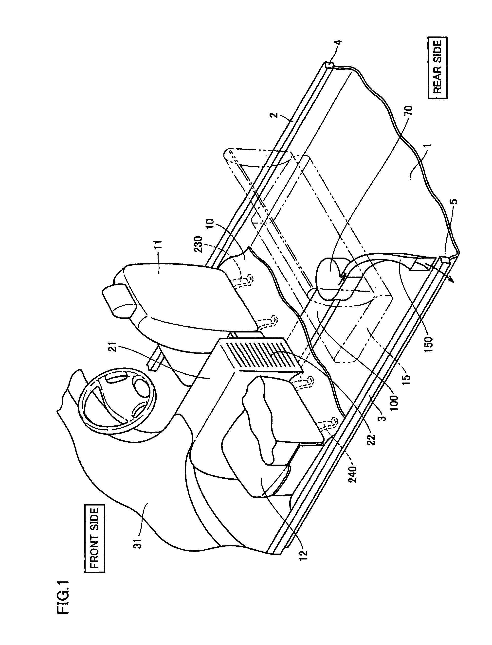
[0024]A first embodiment of the present invention will now be described with reference to FIGS. 1 to 4. FIG. 1 is a perspective view showing a structure inside a vehicle compartment. FIG. 1 shows a hybrid vehicle powered by an internal combustion engine such as a gasoline engine or a diesel engine and by a chargeable and dischargeable power source.

[0025]In the vehicle compartment, a driver seat 11 and a front passenger seat 12 as a front seat according to the present embodiment are arranged aside in the widthwise direction of the vehicle, as shown in FIG. 1. Driver seat 11 and front passenger seat 12 are secured to a floor panel 1 by means of seat legs 230 and seat legs 240, respectively. A floor carpet 10 is provided on the surface of floor panel 1. Floor carpet 10 is arranged so as to cover seat legs 230 and 240. In the present embodiment, floor carpet 10 has its surface sloped downward in a leg area between the front seat and a rear seat 15.

[0026]Provided between floor panel 1 an...

second embodiment

[0059]FIG. 5 is a perspective view showing a vehicle-mounted battery cooling structure according to the present embodiment. In the present embodiment, a single-stage battery pack 60 is provided. Further, flow passages of cooling air within battery pack 60 have the vertical flow configuration.

[0060]Within battery pack 60 shown in FIG. 5, battery modules 44 are aligned adjacent to one another in the front-to-rear direction of the vehicle, similarly to the first embodiment. The flow passages for flowing cooling air are provided between adjacent battery modules 44. In the present embodiment, the flow passages communicate vertically.

[0061]An intake chamber is provided at the upper part within battery pack 60. An exhaust chamber is provided at the lower part within battery pack 60. The flow path has its upper end communicating with the intake chamber and its lower end communicating with the exhaust chamber.

[0062]An air intake port 65 is provided at the upper part on the back face of batte...

third embodiment

[0064]FIG. 6 is a plan view showing a vehicle-mounted battery cooling structure according to the present embodiment. The vehicle-mounted battery cooling structure according to the present embodiment differs from that of the first embodiment by the configuration of exhaust chamber 47 provided in battery pack 40, the configuration of exhaust duct 100 communicating with exhaust chamber 47, and the arrangement of cooling fan 70 and discharge duct 150.

[0065]In the present embodiment, exhaust duct 100 is connected to a side face of exhaust chamber 47, as shown in FIG. 6. Cooling air flowing through intake chamber 46 toward the front of the vehicle flows laterally through flow passages between adjacent battery modules 44. Upon reaching exhaust chamber 47, the cooling air flows through exhaust chamber 47 to a position where exhaust duct 100 is connected.

[0066]Exhaust duct 100 extends laterally from exhaust chamber 47, and is bent rearwards to extend linearly in the rear direction. Cooling f...


PUM


Abstract

A vehicle-mounted battery cooling structure of the present invention includes a battery a cooling fan for cooling the battery, a cooling-medium channel connecting the battery and the cooling fan, and mounting areas located at a front seat side and a rear seat side, respectively, in a vehicle compartment. The battery is disposed in one of the mounting areas, and the cooling fan is disposed in the other one of the mounting areas.

Description

TECHNICAL FIELD[0001]The present invention relates to a vehicle-mounted battery cooling structure, and more particularly to a vehicle-mounted battery cooling structure including a battery and a cooling fan.BACKGROUND ART[0002]A battery mounted on a hybrid vehicle or an electric vehicle generates heat during charging and discharging. Accordingly, some conventional vehicle-mounted batteries are provided with a cooling structure. Such a vehicle-mounted battery cooling structure is disclosed, for example, in Japanese Patent Laying-Open No. 2005-306239 (Patent Document 1).[0003]Patent Document 1 (see FIG. 9) discloses a cooling structure in which a battery 301 is disposed between a driver seat and a front passenger seat to guide cooling air from battery 301 toward the front passenger seat by means of a fan 302.DISCLOSURE OF THE INVENTION[0004]With the conventional battery cooling structure mentioned above, battery 301 and fan 302 are arranged in a limited space at a front seat including ...

Claims


Application Information

Patent Timeline
Patent Type & Authority Patents(United States)
IPC IPC(8): B60R16/04
CPCB60K1/04B60K2001/005B60K2001/0411B60K2001/0427B60K2001/0433
Inventor NAGATA, SHUICHIYAMANAKA, TAKASHI
Owner TOYOTA JIDOSHA KK
Why Eureka
Try Eureka