Systems and methods for reducing flicker noise in an oscillator

a technology of flicker noise reduction and oscillator, applied in the field of digital control of oscillators, can solve the problems of reducing the tuning range and circuits typically suffering from substantial flicker noise, and achieve the effect of selectively incorporating capacitance and reducing flicker nois

Active Publication Date: 2011-10-25
TEXAS INSTR INC
View PDF7 Cites 19 Cited by
  • Summary
  • Abstract
  • Description
  • Claims
  • Application Information

AI Technical Summary

Benefits of technology

[0006]Various embodiments of the present invention provide LC tank circuits. Such circuits include an inductance and a capacitance. In addition, the circuits include a switch that has reduced flicker noise and is operable to selectively incorporate the capacitance such that an output of the circuit operates at a frequency based on a combination of the inductance and the selected capacitance.

Problems solved by technology

Such circuits typically suffer from substantial flicker noise, and parasitic capacitances that effectively reduce the offered tuning range of an oscillator switching capacitance in and out to control a frequency output.

Method used


Image

  • Systems and methods for reducing flicker noise in an oscillator
  • Systems and methods for reducing flicker noise in an oscillator
  • Systems and methods for reducing flicker noise in an oscillator

Examples


Embodiment Construction

[0023]The present invention is related to oscillators, and more particularly to digitally controlled oscillators.

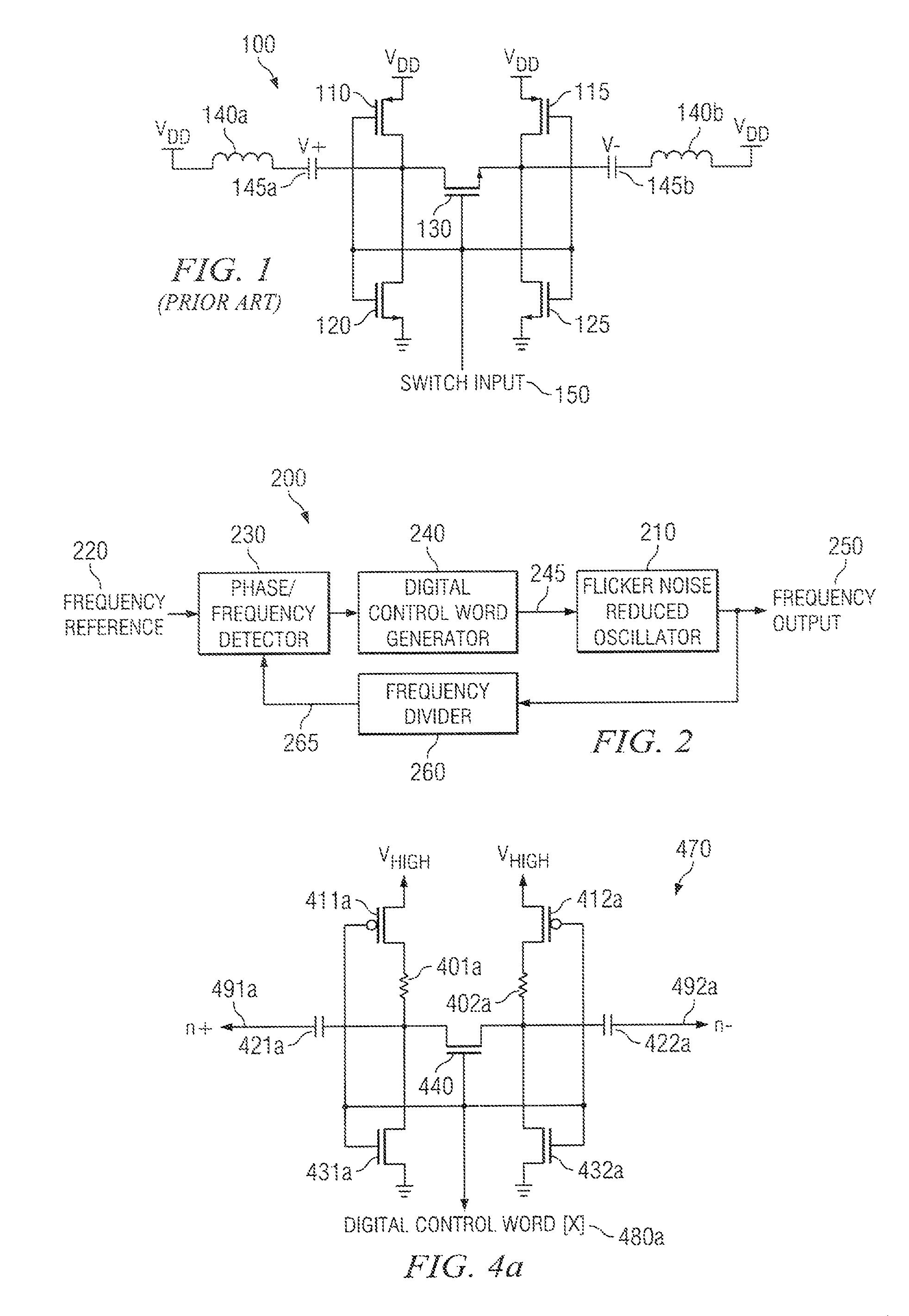
[0024]Referring to the circuit of FIG. 1, in the on-state (i.e., where a high voltage is applied to the gate of N-type transistor 130), the DC bias voltages on the source and drain of N-type transistor 130 are not well defined if the N-type transistors 120 and 125 are not present. In some cases, such ill-defined bias voltages may prevent a proper impedance change on N-type transistor 130, or may cause the effective capacitance of the LC oscillator to slowly vary with time impacting stability of the oscillator and effective frequency tuning range of the oscillator. To avoid this, the source and drain of N-type transistor 130 may be anchored at zero volts during the on-state. This may be accomplished by using N-type transistors 120 and 125 with a low on-state resistance. In the off-state, N-type transistor 130 is effectively removed from the circuit. Thus, the voltage swing...


PUM


Abstract

Various systems and methods for implementing dynamic logic are disclosed herein. For example, some embodiments of the present invention provide LC tank circuits having an inductance and a capacitance. In addition, the circuits include a flicker noise reducing switch that is operable to selectively incorporate the capacitance such that an output of the circuit operates at a frequency based on a combination of the inductance and the capacitance.

Description

BACKGROUND OF THE INVENTION[0001]The present invention is related to oscillators, and more particularly to digitally controlled oscillators.[0002]Oscillators are incorporated into a number of different products and can be used, for example, to generate clocks that synchronize various circuit operations. Due to stringent phase noise requirements, most Radio Frequency (RF) oscillators for wireless communication are implemented using an LC resonator. An exemplary prior art LC tank circuit 100 (i.e., a varactor circuit with inductors) is shown in FIG. 1. LC tank circuit 100 includes two P-type transistors 110, 115, and three N-type transistors 120, 125, 130. In addition, tank circuit 100 includes an inductance 140 and a capacitance 145. The gates of N-type transistor 120, N-type transistor 125, N-type transistor 130, P-type transistor 110 and P-type transistor 115 are all electrically coupled to a switch input 150. The drain of P-type transistor 110 is electrically coupled to the drain ...

Claims


Application Information

Patent Timeline
Patent Type & Authority Patents(United States)
IPC IPC(8): H03B5/12
CPCH03L7/0991H03B5/1228H03B5/1215H03B2200/0088
Inventor BARTON, NATHENHUNG, CHIH-MING
Owner TEXAS INSTR INC
Why Eureka
Try Eureka