

Method for regulating OSNR in a fiber optic communication line using Raman amplification
a technology of raman amplification and fiber optic communication line, applied in the direction of basic electric elements, laser details, electrical apparatus, etc., to achieve the effect of effective framing
- Summary
- Abstract
- Description
- Claims
- Application Information
AI Technical Summary
Benefits of technology
Problems solved by technology
Method used
Image

Examples
Embodiment Construction
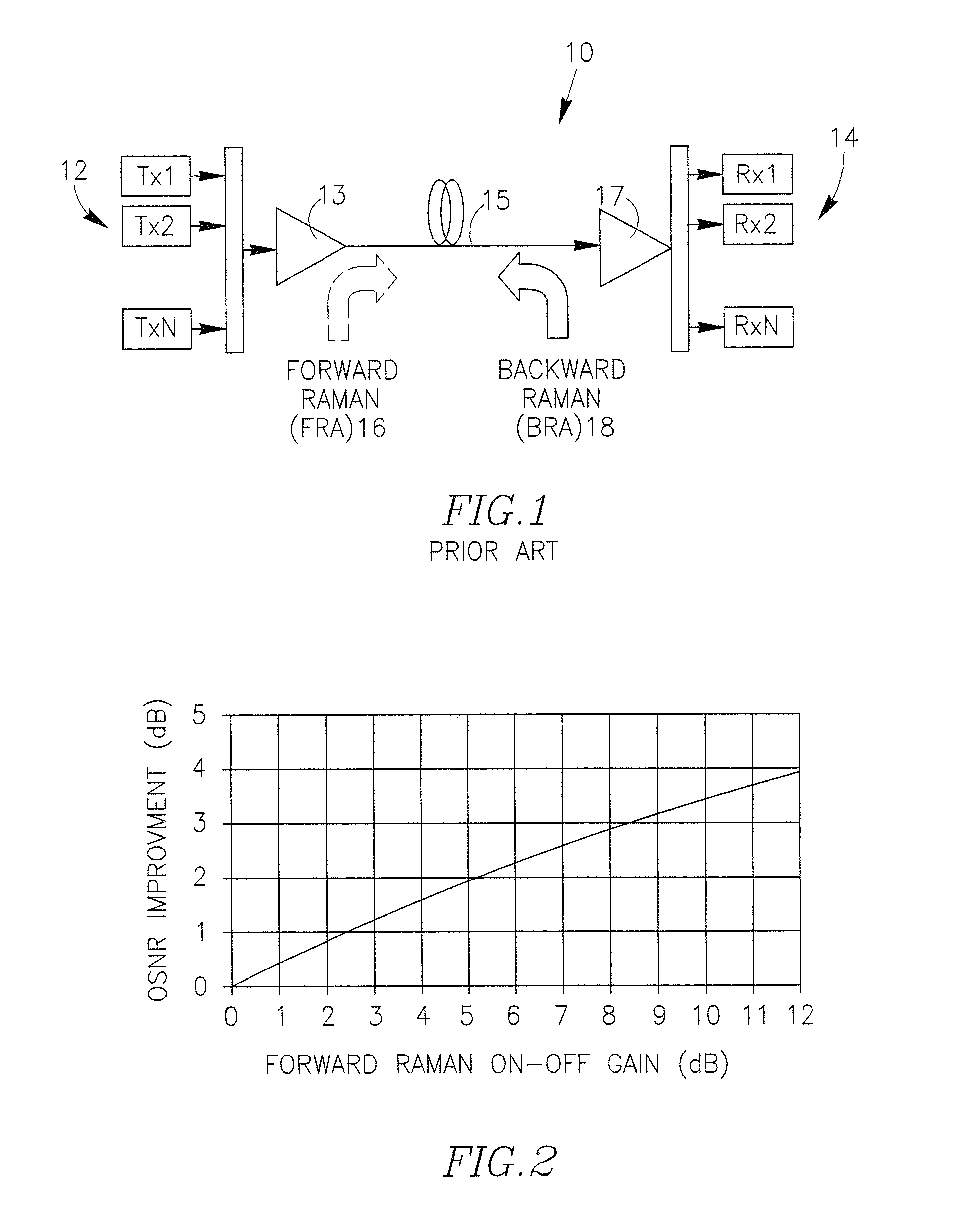
[0073]FIG. 1 is referred to in the Background description.
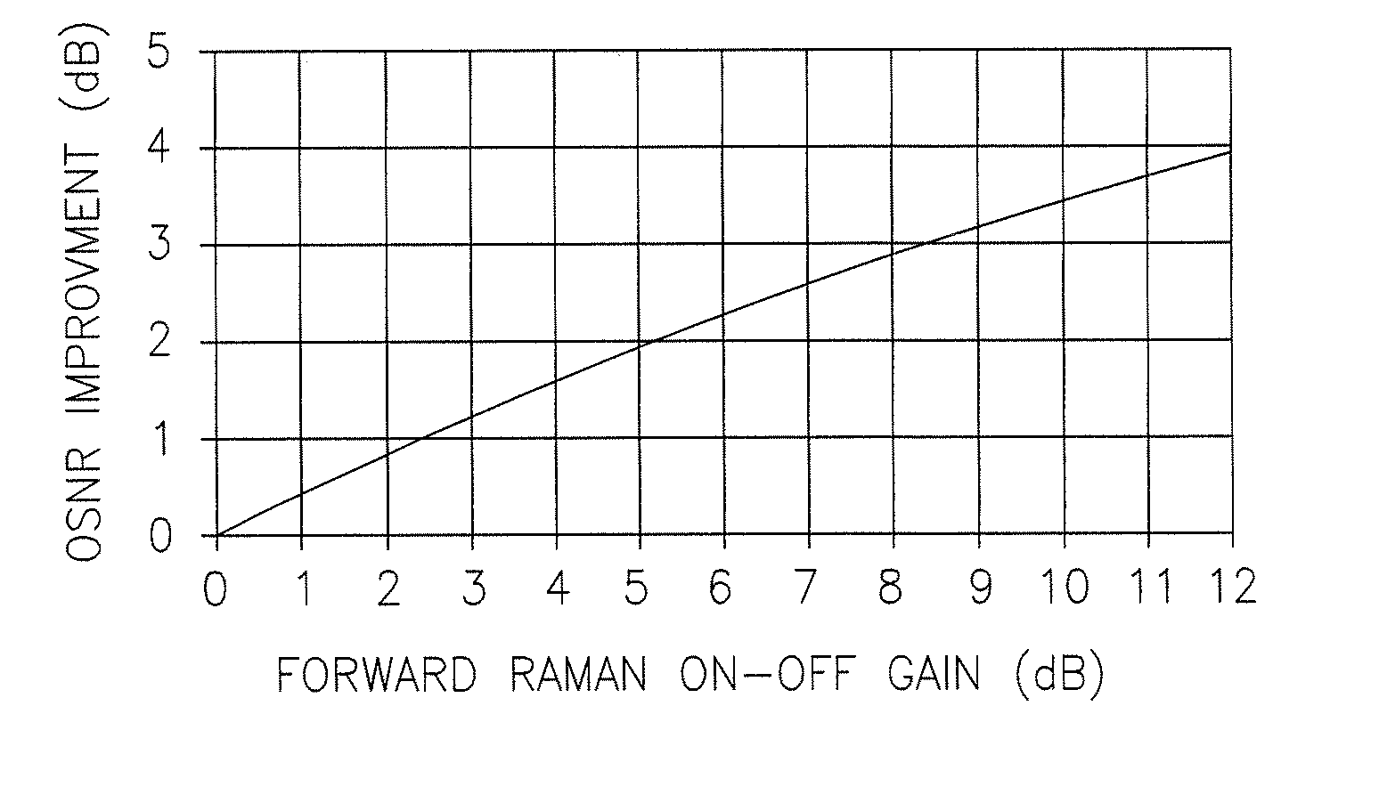
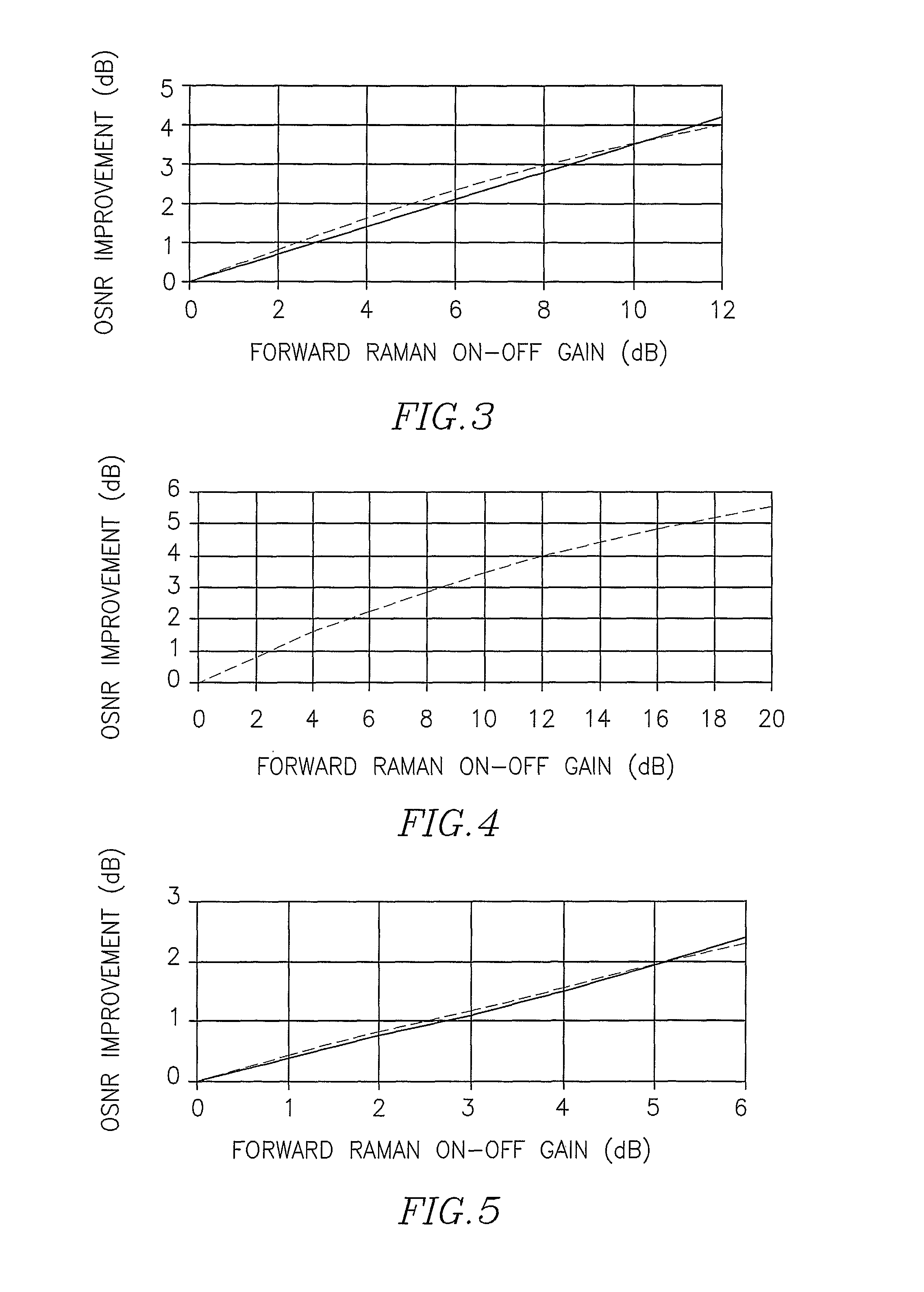
[0074]FIG. 2 graphically presents the regulation function proposed by the Inventor for determining the minimal on-off gain of a FRA, if associated with a transmitting end of a long fiber optic transmission line required to achieve a certain OSNR improvement at the receiving end of the optical fiber span.
[0075]An exemplary long fiber optic transmission line is shown in FIG. 1 as a single span (15).
[0076]Let us consider for our example, that the line satisfies the following two conditions: it operates under a non-linearity limit (without any non-linearity effects), and its fiber loss L is much greater than the maximal gain Gm of the FRA (16). If, for example the Gm of the existing FRA is 10 dB, the method can be applied quite accurate when the line is long enough to create fiber loss of about 20 dB or more. And vice versa, if quite a long given transmission line is not yet provided with Raman amplifiers and requires specific OS...
PUM
 Abstract
Description
Claims
Application Information