
Active optical fibers with wavelength-selective filtering mechanism, method of production and their use

a wavelength-selective filtering and active optical fiber technology, applied in the field of optical waveguides, can solve the problems of multiple optical components, difficult to obtain amplification for parts of the emission spectrum, and limited wavelengths available for amplification, so as to achieve the effect of reducing or preferably suppressing amplified spontaneous emission at undesired wavelengths and improving amplification efficiency

Active Publication Date: 2011-10-25
NKT PHOTONICS
View PDF27 Cites 9 Cited by
  • Summary
  • Abstract
  • Description
  • Claims
  • Application Information

AI Technical Summary

Benefits of technology

The present invention provides improved active optical fibers for amplifier and laser applications that reduce or suppress amplified spontaneous emission at undesired wavelengths, allowing for more efficient amplification at desired wavelengths. The fibers have a core region with active material that allows for optical amplification and are designed to guide light by the photonic bandgap effect. The fiber has a transmission spectrum with one or more pass bands and at least one stop-band, and the active material has a higher emission cross section at a wavelength within the stop-band than outside it. This reduces amplified spontaneous emission and lasing in the stop-band. The fiber is adapted to amplify and guide light at a signal wavelength located in a pass band.

Problems solved by technology

However, the available wavelengths for amplification are limited by the available emission spectrum of the specific rare-earth ions.
One common problem for optical amplifiers is that it is difficult to obtain amplification for parts of the emission spectrum, where the emission cross-sections of rare-earth ions are significantly below their peak values.
The problem is that amplified spontaneous emission at undesired wavelengths (where the emission cross-sections are high) can dominate over the stimulated emission at a desired (e.g. signal) wavelength (with a lower emission cross-section).
It is, however, a disadvantage that multiple optical components are required to filter away the undesired amplified spontaneous emission.
Further, there are in practice limits to power levels and wavelengths that can be obtained in this way.

Method used


Image

  • Active optical fibers with wavelength-selective filtering mechanism, method of production and their use
  • Active optical fibers with wavelength-selective filtering mechanism, method of production and their use
  • Active optical fibers with wavelength-selective filtering mechanism, method of production and their use

Examples


Embodiment Construction

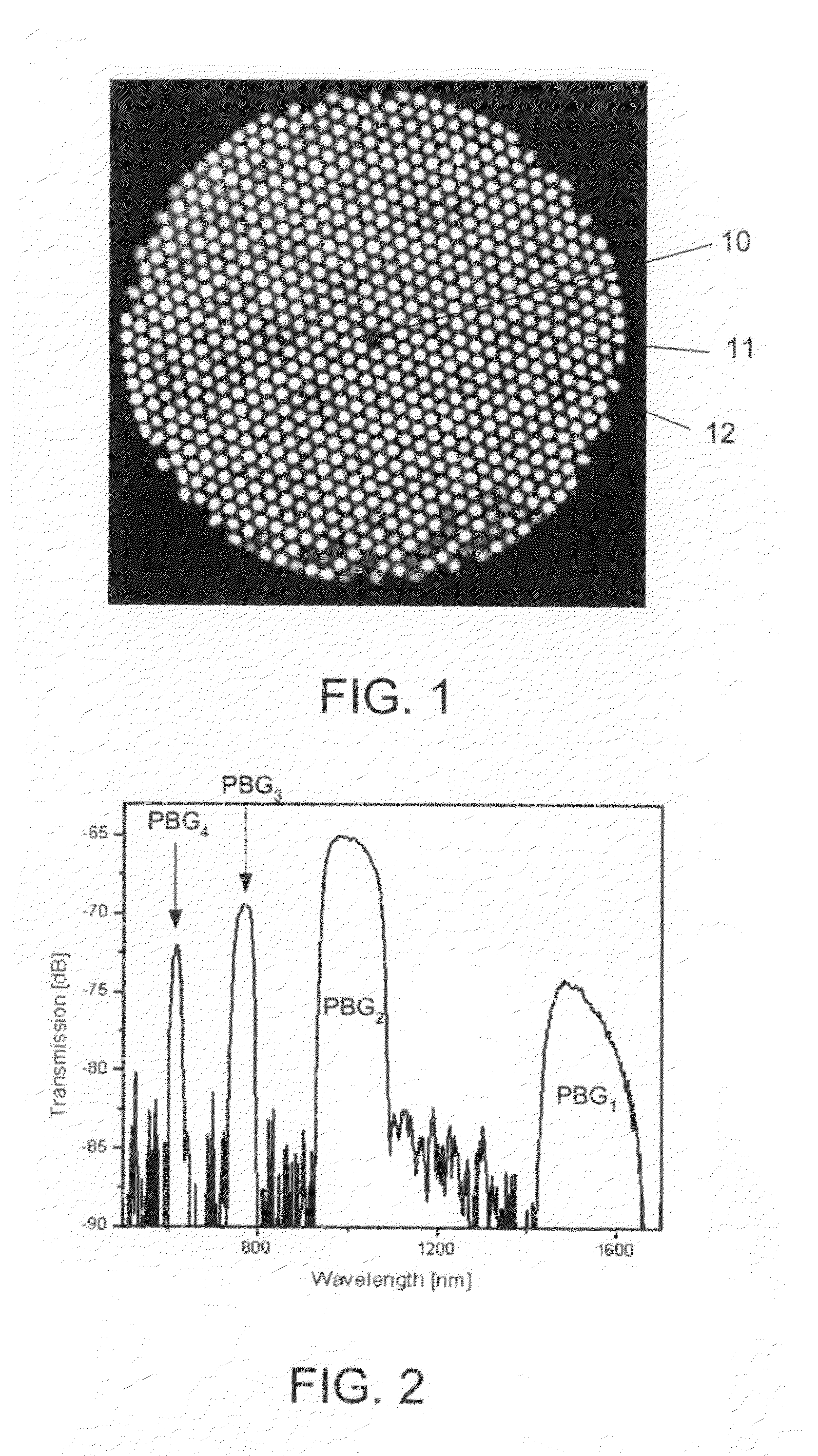
[0232]FIG. 1 shows a microscope picture of a solid PBG fiber as described in WO-02 / 101429 (‘a solid PBG fiber’ meaning a PBG fiber that does not rely on voids to achieve the PBG-effect). The PBG fiber comprises a solid core 10 surrounded by a cladding region comprising a substantially 2D periodic arrangement of high-index, solid elements 11 (light areas in picture) dispersed in a low-index cladding background material 12. The fiber of the present example has a pure silica core 10, Ge-doped rods 11 positioned in a triangular lattice in a pure silica background material 12 and around 15 periods surrounding the core region. The present invention also covers other means of forming pass and stop bands, e.g. including fibers having instead of a triangular arrangement, a rectangular (e.g. quadratic) or hexagonal (i.e. planar or 2D-periodic) or circular (e.g. radially periodic, including concentric regions of different (e.g. alternating) refractive indices) arrangement of high-index element...


PUM


Abstract

The invention relates to optical fibers for use in optical amplification of light, such as in optical fiber amplifiers and lasers and for use in delivery of high power light, in particular to a scheme for reducing amplified spontaneous emission at undesired wavelengths. The invention further relates to articles, methods and use. An object of the invention is achieved by a micro-structured optical fiber, which is adapted to guide light by the photonic bandgap effect and to have one or more pass bands and at least one stop-band over a wavelength range from λstop1 to λstop2. In an aspect of the invention, the at least one stop-band provides filter functions that suppress nonlinear effects. In another aspect, the core region is actively doped, and the active material has an emission spectrum with a higher value of the emission cross section σE at a wavelength λASE between λstop1 and λstop2 than outside said wavelength range such that amplified spontaneous emission and lasing within the wavelength range from λstop1 to λstop2 is reduced. In still another aspect, the optical fiber exhibits photonic bandgaps at different wavelength ranges in different radial directions of a cross section of the optical fiber.

Description

TECHNICAL FIELD[0001]The present invention is in the field of optical waveguides and relates in particular to optical waveguides for use in optical amplification of light, such as in optical fiber amplifiers and in optical fiber lasers, and for use in delivery of high power light.BACKGROUND ART[0002]Optical fiber waveguides, which are able to amplify light have been explored over the last decades for a number of applications (see e.g. Michel J. F. Digonnet, ed., “Rare-Earth-Doped Fiber Lasers and Amplifiers”, 2nd edition, 2001, Marcel Dekker, Inc., New York-Basel, referred to elsewhere in this application as [Digonnet]). For optical communication systems, for example, fiber optical amplifiers are used, where Erbium ions are incorporated into an optical fiber to provide amplification of light around 1.5 μm. For amplification at other wavelengths other rare-earths, such as Yb, Nd, Ho, Tm, and others are used. Other means of amplification than using rare-earth ions are also possible, f...

Claims


Application Information

Patent Timeline
Patent Type & Authority Patents(United States)
IPC IPC(8): H04B10/17G02B6/036G02B6/134H04B10/12
CPCG02B6/02323G02B6/02338G02B6/02347G02B6/02357G02B6/0238H01S3/06708G02B6/02366H01S2301/02
Inventor PETERSSON, ANDERSBROENG, JESKRISTIANSEN, RENE ENGEL
Owner NKT PHOTONICS
Learn More