Mask blank glass substrate, mask blank glass substrate manufacturing method, mask blank manufacturing method, and mask manufacturing method

a technology of glass substrate and manufacturing method, applied in the field of mask blank glass substrate, mask blank glass substrate manufacturing method, mask blank manufacturing method, etc., can solve the problems of generating dust, becoming difficult to meet the quality requirements of mask blanks or mask blank glass substrates, etc., to suppress the lowering of the strength of portions, suppress the generation of dust, and suppress the effect of lowering the strength

Inactive Publication Date: 2011-11-01
HOYA CORP
View PDF15 Cites 2 Cited by
  • Summary
  • Abstract
  • Description
  • Claims
  • Application Information

AI Technical Summary

Benefits of technology

[0006]It is therefore an object of this invention to provide a mask blank glass substrate, a mask blank glass substrate manufacturing method, a mask blank manufacturing method, and a mask manufacturing method that can solve the above-mentioned problem.
[0052]According to this invention, by forming each of pits by a round hole with its edge portion having no vertex and being generally circular in a plan-view shape, it is possible to suppress lowering of the strength and, by setting the distance between the adjacent pits to a predetermined value or more, it is possible to suppress lowering of the strength of portions between the adjacent pits, thereby making it possible to provide a mask blank glass substrate that can suppress the generation of dust due to cracks, chips, or the like at a marker forming portion.

Problems solved by technology

However, when forming a marker on a mask blank glass substrate, there is a possibility that, depending on the shape of the marker or the manner of formation of the marker, dust is generated during the formation of the marker or in subsequent processes.
Then, if the dust is generated during the formation of the marker or in the subsequent processes, there is a possibility that it becomes difficult to satisfy the quality required for a mask blank or a mask blank glass substrate.

Method used


Image

  • Mask blank glass substrate, mask blank glass substrate manufacturing method, mask blank manufacturing method, and mask manufacturing method
  • Mask blank glass substrate, mask blank glass substrate manufacturing method, mask blank manufacturing method, and mask manufacturing method
  • Mask blank glass substrate, mask blank glass substrate manufacturing method, mask blank manufacturing method, and mask manufacturing method

Examples


example 1

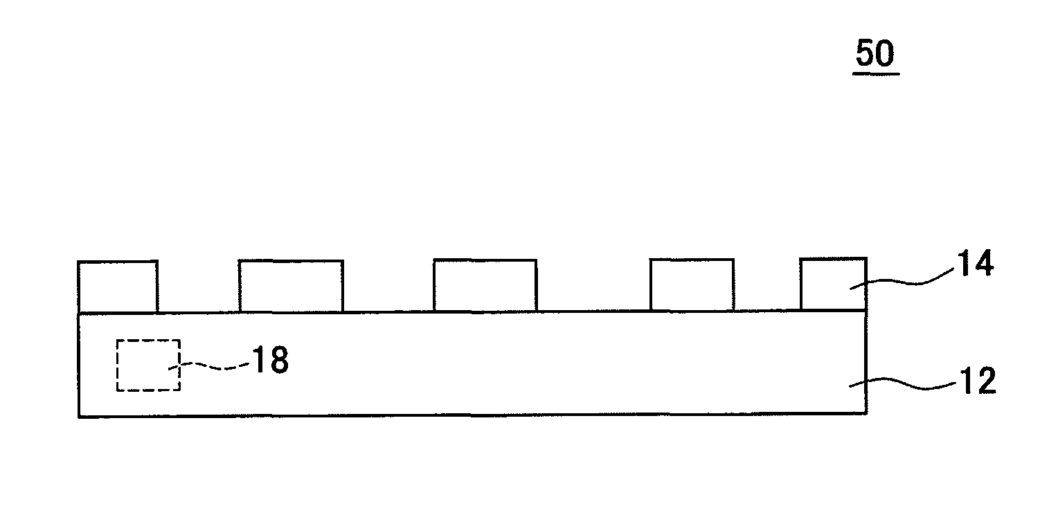
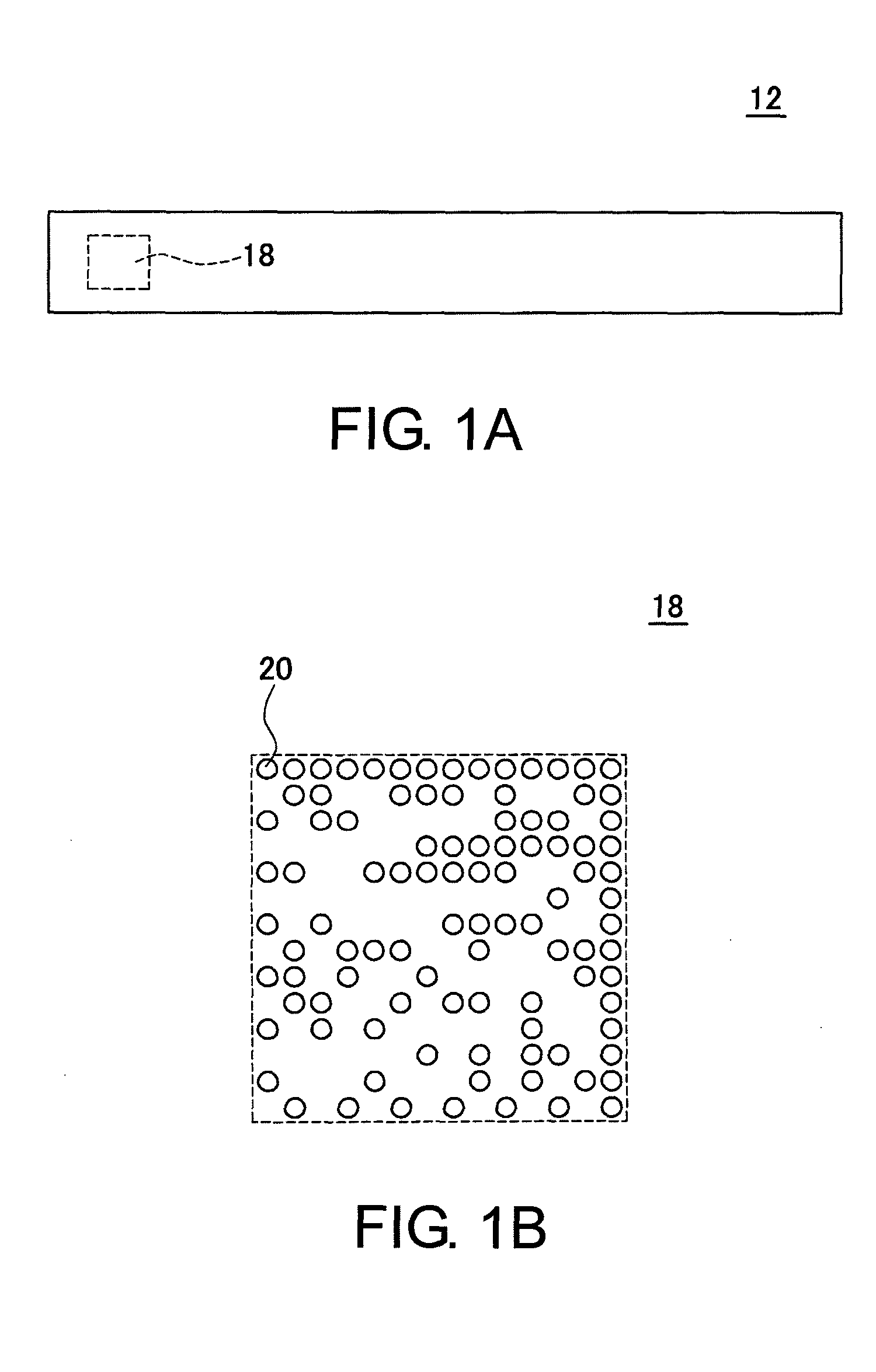
[0094]A glass substrate 12 according to Example 1 was manufactured in the same or similar manner as a known mask blank glass substrate manufacturing method except that a laser irradiation process was carried out for forming a marker 18. In this Example, an end face polishing process of polishing an end face of the glass substrate 12 to a predetermined surface roughness was carried out, for example, in the same or similar manner as a known end face polishing process. The laser irradiation process was carried out prior to the end face polishing process. Accordingly, in the end face polishing process, the end face formed with pits 20 by irradiation of laser light was polished to the predetermined surface roughness.

[0095]Further, in this Example, in the same or similar manner as the method described with reference to FIGS. 4A and 4B, the laser irradiation process was carried out by adjusting the irradiation intensity and so on of a laser marker and irradiating carbon dioxide laser light...

example 2

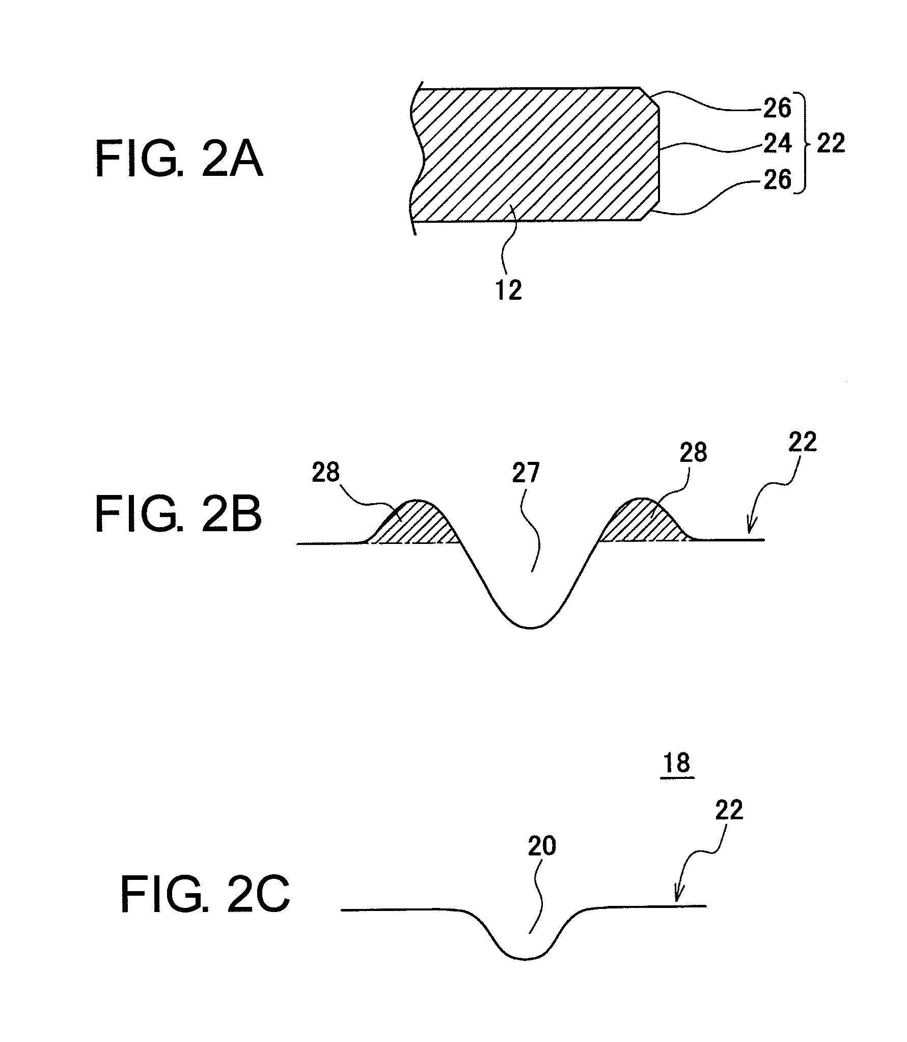
[0098]A glass substrate 12 according to Example 2 was manufactured in the same manner as in Example 1 except that the diameter of laser light was set to 0.06 mm. Also in Example 2, as in Example 1, each pit 20 was formed as a hole being generally circular in plan view and having a generally V-shaped section. The diameter L1 of each pit 20 at its edge portion and the depth D thereof also fell within substantially the same ranges as those in Example 1.

example 3

[0099]A glass substrate 12 according to Example 3 was manufactured in the same manner as in Example 1 except that various conditions were adjusted so that the average distance between edge portions of adjacent pits 20 became 100 μm (in the laser marker, the diameter of laser light was adjusted to 0.1 mm and various settings such as the laser power and the scan speed were adjusted so that the shape of each pit 20 became the preferable shape as shown in FIGS. 3A and 3B).

[0100]As a result, in Example 3, each pit 20 was formed as a hole being generally circular in plan view and having a generally V-shaped section as shown in FIGS. 3A and 3B. The diameter L1 of each pit 20, forming a marker 18, at its edge portion took a value in a range of 145 to 155 μm (150 μm in average). In this case, the average distance between the edge portions of the adjacent pits 20 was 100 μm. The depth D of each pit 20 was 25 to 40 μm (29 μm in average).


PUM

PropertyMeasurementUnit
depthaaaaaaaaaa
diameteraaaaaaaaaa
distanceaaaaaaaaaa

Abstract

A mask blank glass substrate is for use in manufacturing a mask blank. In the mask blank glass substrate, a marker expressing, by a plurality of pits, information for identifying or managing the mask blank glass substrate is formed on a surface of a region, having no influence on formation of a transfer pattern, of the mask blank glass substrate. Each of the pits forming the marker is a round hole with its edge portion being generally circular and a distance L1 between the edge portions of the adjacent pits is 50 μm or more. The marker is formed, for example, on an end face of the mask blank glass substrate.

Description

[0001]This application is based upon and claims the benefit of priority from Japanese Patent Application No. 2008-158765, filed on Jun. 18, 2008, the disclosure of which is incorporated herein in its entirety by reference.TECHNICAL FIELD[0002]This invention relates to a glass substrate for a mask blank (hereinafter referred to as a “mask blank glass substrate”), a mask blank glass substrate manufacturing method, a mask blank manufacturing method, and a mask manufacturing method.BACKGROUND ART[0003]A structure is known in which a marker for identification or management is formed on a mask blank glass substrate for use in the manufacture of a mask blank (see, e.g. Japanese Unexamined Patent Application Publication (JP-A) No. 2006-309143 (Patent Document 1) corresp. to US2006 / 0246361A1). This marker is expressed by an array of pits. The pits are formed by laser light irradiation on a surface of a region, having no influence on formation of a transfer pattern, of a mask blank glass subs...

Claims


Application Information

Patent Timeline
Patent Type & Authority Patents(United States)
IPC IPC(8): G03F1/00C03C23/00G03F1/50G03F1/60
CPCG03F1/38G03F1/14G03F1/60G03F1/44G03F1/76
Inventor KASAHARA, HISASHIOKUBO, YASUSHI
Owner HOYA CORP
Why Eureka
Try Eureka