
Magneto-rheological damper

Inactive Publication Date: 2011-11-08
HONDA MOTOR CO LTD
View PDF14 Cites 15 Cited by
  • Summary
  • Abstract
  • Description
  • Claims
  • Application Information

AI Technical Summary

Benefits of technology

[0008]In view of such problems of the prior art, a primary object of the present invention is to provide a variable damper which can be made highly compact without impairing the performance of the damper.
[0009]A second object of the present invention is to provide a variable damper which can vary the damping force thereof over a wide range.
[0010]A third object of the present invention is to provide a variable damper which is durable in use.

Problems solved by technology

However, the saturation magnetic flux density of carbon steel is not very high so that the variable range of the damping force cannot be made so wide as desired.
The inventors experimented the use of soft magnetic materials including iron-cobalt alloy (such as Permendur) having high saturation magnetic flux densities, but such materials do not have a high hardness, and have relatively poor elongation and drawing properties.
Therefore, such materials were not found to be suitable for use in the outer yoke of conventional magneto-rheological dampers.
More specifically, if material such as Permendur is used for the outer yoke which forms the outermost shell of the piston in the damper disclosed in U.S. Pat. No. 6,260,675, because the outer circumferential surface of the outer yoke constantly slides over the inner circumferential surface of the cylinder during use, the outer yoke wears out very rapidly.
Wear in the outer yoke creates a play between the piston and cylinder in time, and this play not only causes noises but also reduces the damping force due to leakage of magnetic fluid through the play between the piston and cylinder.
However, material such as Permendur having a poor drawing property is not suitable for crimping.

Method used


Image

  • Magneto-rheological damper
  • Magneto-rheological damper
  • Magneto-rheological damper

Examples


second embodiment

[0037]FIG. 6 shows the present invention. The parts corresponding to those of the previous embodiment are denoted with like numerals without repeating the description of such parts to avoid redundancy.

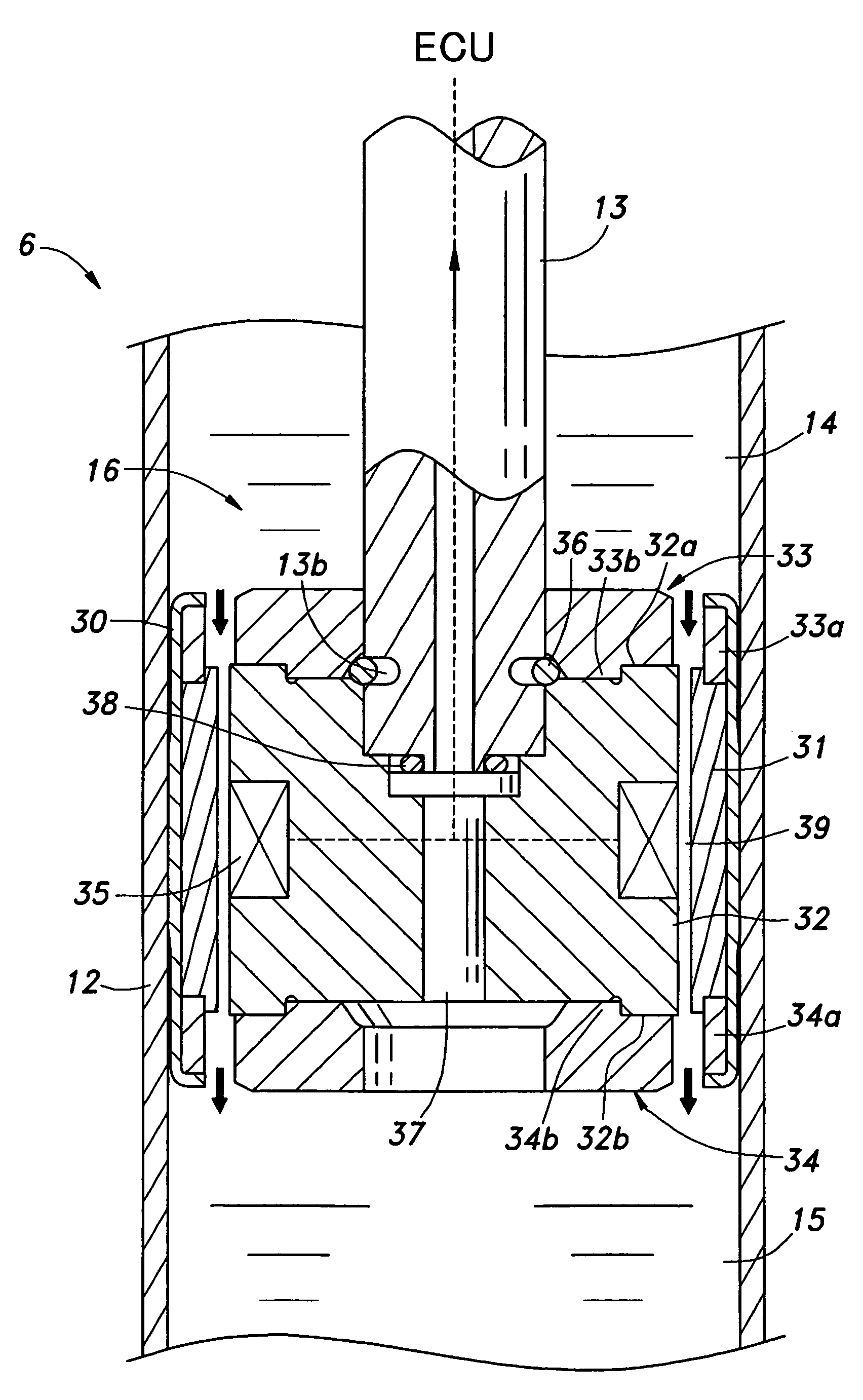
[0038]In the second embodiment, no piston cover is used. The end plates 33 and 34, inner yoke 32 and outer yoke 31 are held integrally together by a plurality of threaded bolts 40 passed axially through the end plates 33 and 34 and inner yoke 32. In this embodiment also, the outer yoke 31 is made of Permendur, and the outer circumferential thereof opposes the inner circumferential surface of the cylinder 12 with an annular gap defined therebetween owing to the end plates 33 and 34 that clamp the inner yoke 32 between them. The end plates 33 and 34 have a larger outer diameter than the outer yoke 31 so that the outer circumferential surfaces of the end plates 33 and 34 are in sliding engagement with the inner circumferential surface of the cylinder 12 while the outer circumferential sur...

third embodiment

[0039]FIG. 7 shows the present invention. The piston 16 comprises a substantially solid cylindrical inner yoke 126 made of magnetic material, and an end of the piston rod 13 is received in a hole 135 formed centrally in an axial end of the inner yoke 126. The inner yoke 126 consists of axially separated two parts 126a and 126b which are integrally and axially joined to each other by four threaded bolts 127 passed into the inner yoke 126 from the axial end remote from the piston rod 113.

[0040]The outer circumferential surface of the inner yoke 126 is formed with an annular groove 128 in an axially central part thereof, and a coil 130 is received therein via a coil bovine 129. In this case also, the coil 130 is wound in the circumferential direction, and molded in resin. The outer peripheral part of the annular groove 128 is provided with axial extensions 131 formed by extending parts of the inner yoke 126 from the both axial ends into the peripheral part of the coil 130. In the illus...


PUM


Abstract

In a magneto-rheological variable damper (6), the piston (16) comprises an inner yoke (32), an outer yoke (31) concentrically surrounding the inner yoke and held in position by pair of end plates (33, 34) made of non-magnetic material and disposed on either axial end surfaces of the piston. The piston may be circumferentially surrounded by a piston cover (30) that may be made of non-magnetic material and serves a slide member that engages the inner circumferential surface of a cylinder (12). Alternatively, the end plates may serve as the slide member. In either case, the durability of the damper can be improved by using a wear resistant material for the slide member. In particular, the outer yoke may be made of material such as Permendur which has a high saturation magnetic flux density but a poor mechanical property. Thereby, the range of the damping force can be expanded. The slide member may be made of non-magnetic material having a favorable wear resistance such as austenite stainless steel and aluminum alloy. It is also possible to apply a plating or other surface processing to the sliding surface of the slide member to improve the wear resistance thereof.

Description

CROSS REFERENCE TO COPENDING APPLICATION(S)[0001]U.S. patent application Ser. No. 11 / 954,292 filed Dec. 12, 2007TECHNICAL FIELD[0002]The present invention relates to a variable shock absorber or damper that can produce a variable damping force for use in an automotive wheel suspension system, and in particular to a variable damper that is highly durable in use and can vary the damping force over a wide range.BACKGROUND OF THE INVENTION[0003]Various forms of variable dampers have been proposed for use in wheel suspension systems for the purposes of improving the ride quality and achieving a motion stability of the vehicle. In a common conventional variable damper, a rotary valve is incorporated in the piston for varying an effective area of an orifice that communicates the two chambers on either side of the piston with each other, and such a rotary valve is typically actuated mechanically by using a suitable actuator. More recently, it has become more common to use magneto-rheologica...

Claims


Application Information

Patent Timeline
Patent Type & Authority Patents(United States)
IPC IPC(8): F16F9/53
CPCF16F9/535
Inventor AZEKATSU, YOSHITOMOKAJIWARA, HAJIME
Owner HONDA MOTOR CO LTD
Learn More