Camera system for processing luminance and color signals using added pixel and adding sync signals

a color camera and luminance technology, applied in the field of high-sensitivity three-plate color camera systems, can solve the problems of deteriorating the horizontal resolution compared with the case, pixel addition process, and relatively large positional irregularities, and achieve the effect of high precision

Inactive Publication Date: 2011-11-08
SONY CORP
View PDF12 Cites 4 Cited by
  • Summary
  • Abstract
  • Description
  • Claims
  • Application Information

AI Technical Summary

Benefits of technology

[0013]However, since the luminance signals are mainly composed of G signals, as shown in FIG. 12B, in the high-sensitive color camera system 300, the G pixels are separated from each other by a gap corresponding to 2δ (δ corresponds to a gap between adjacent pixels in the solid-state imaging device) in a horizontal direction after the horizontal two-pixel addition process, thereby greatly deteriorating the horizontal resolution compared with the case where the pixel addition process is not performed.
[0015]FIG. 14B shows an arrangement of pixels in a case where the G pixels are shifted from each other in an ideal manner. When the luminance signals are interpolated in such a pixel arrangement, a maximum effective resolution can be achieved. However, a positional irregularity is relatively large in a positioning process of the solid-state imaging device, as shown in FIG. 14C. When the G pixels are shifted to the positions of G′ pixels, the luminance signals Y obtained through the interpolation are shifted toward the vicinity of the B and R pixels as the G′ pixels moves closer to the B and R pixels, thereby decreasing the effective resolution.
[0020]In the camera system according to the second embodiment, pixels of the solid-state imaging devices are electrically shifted from each other by an arbitrary gap in a horizontal direction, in a vertical direction, or in both horizontal and vertical directions by using control signals. Accordingly, it is possible to arrange pixels with high precision.

Problems solved by technology

However, since the luminance signals are mainly composed of G signals, as shown in FIG. 12B, in the high-sensitive color camera system 300, the G pixels are separated from each other by a gap corresponding to 2δ (δ corresponds to a gap between adjacent pixels in the solid-state imaging device) in a horizontal direction after the horizontal two-pixel addition process, thereby greatly deteriorating the horizontal resolution compared with the case where the pixel addition process is not performed.
However, a positional irregularity is relatively large in a positioning process of the solid-state imaging device, as shown in FIG. 14C.

Method used


Image

  • Camera system for processing luminance and color signals using added pixel and adding sync signals
  • Camera system for processing luminance and color signals using added pixel and adding sync signals
  • Camera system for processing luminance and color signals using added pixel and adding sync signals

Examples


Embodiment Construction

[0035]A CCD (charge coupled device)-type imager and a CMOS (complementary metal oxide semiconductor)-type imager are known as the solid-state imaging device, and the embodiments of the invention can be applied to either types of imagers.

[0036]First, a method of controlling a camera system employing the CCD type imager (solid-state imaging device) will be described with reference to FIGS. 1 to 5. In the embodiments, a multi-plate type solid-state imaging device, for example, a three-plate type color camera system will be used as an example of the camera system.

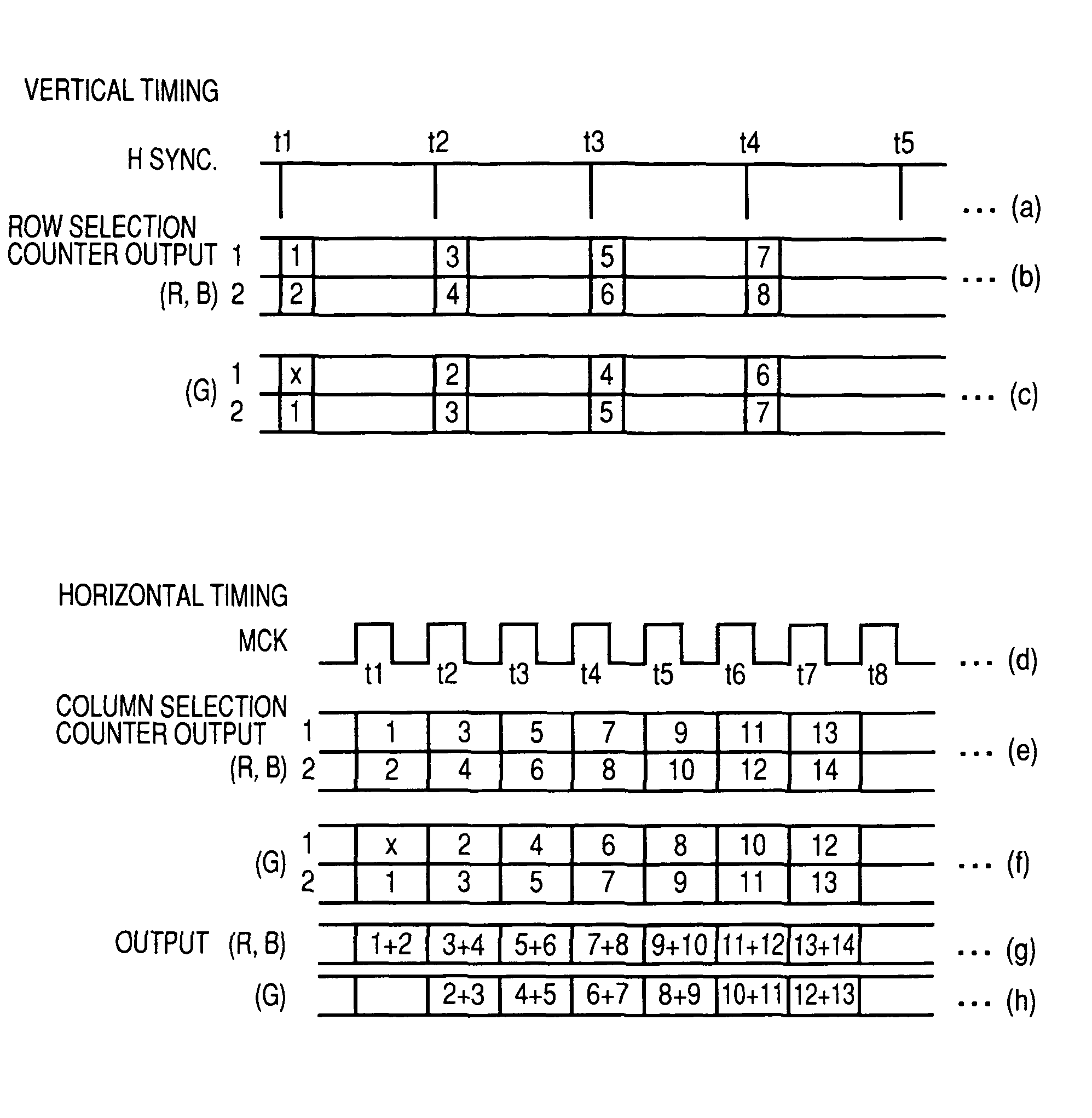
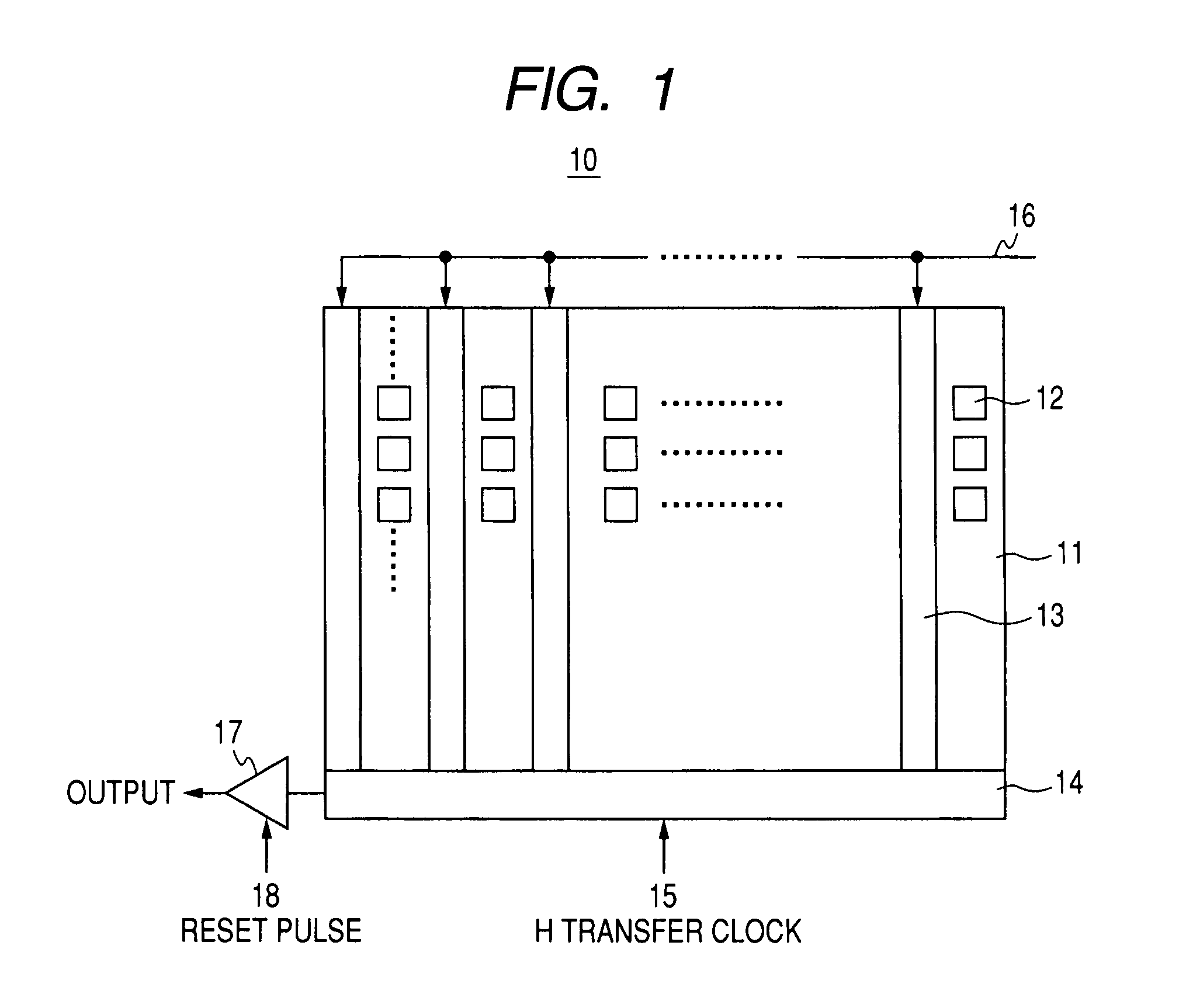
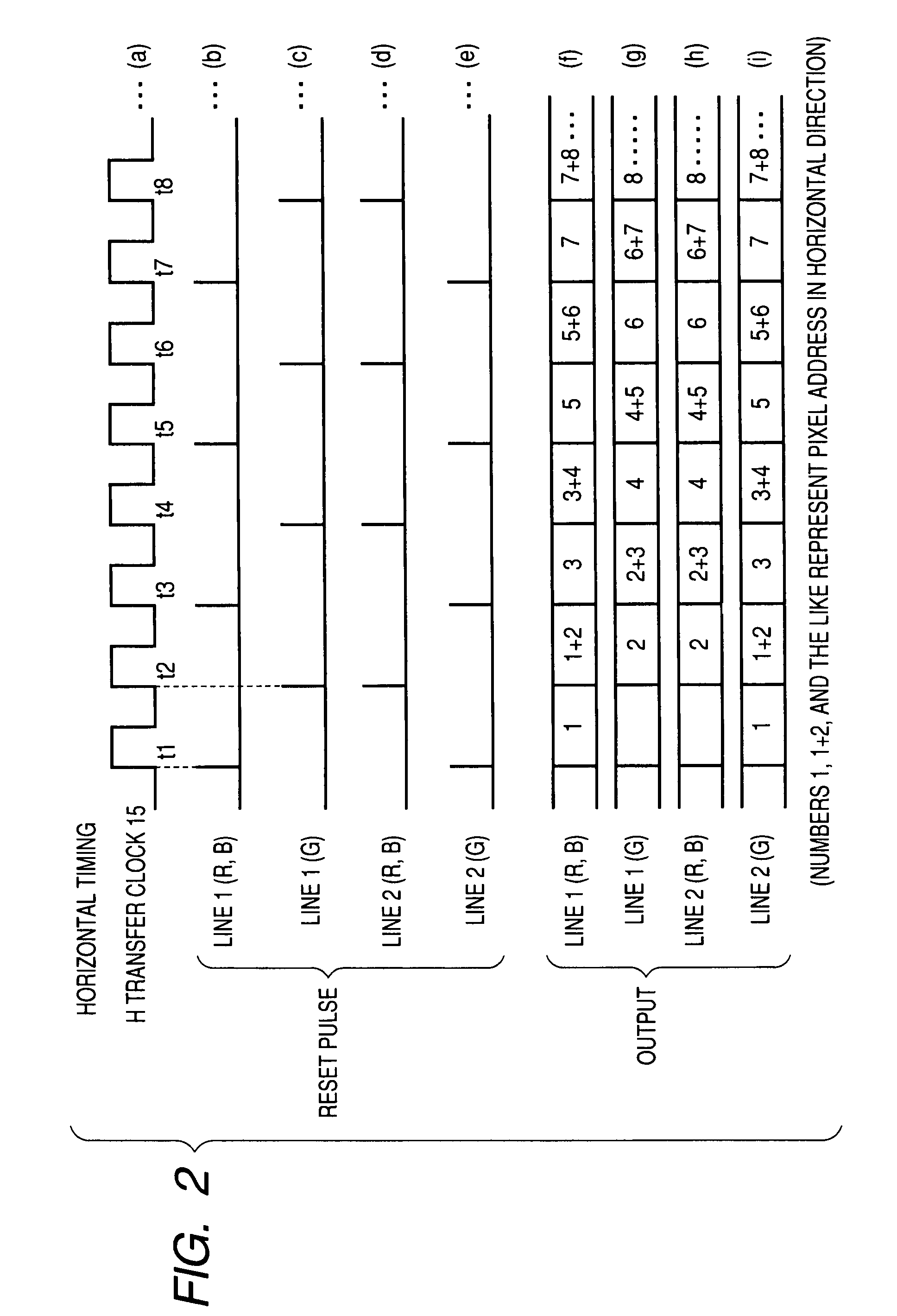
[0037]Hereinafter, the method of controlling the CCD-type camera system according to an embodiment of the invention will be described with reference to FIGS. 1 to 5. In the three-plate type CCD camera system, the solid-state imaging device 11 is configured to have three solid-state imaging devices, that is, an R solid-state imaging device 11R, a B solid-state imaging device 11B, and a G solid-state imaging device 11G.

[0038]In F...


PUM


Abstract

A method of controlling a camera system having a plurality of solid-state imaging devices is provided. The method includes supplying a horizontal addition control signal and a vertical addition control signal, phases of which are controlled, to the plurality of solid-state imaging devices; selecting pixel column(s) and row(s) of the plurality of solid-state imaging devices in accordance with the horizontal addition control signal and the vertical addition control signal; adding a plurality of pixel signals to each other, the plurality of pixel signals being adjacent to each other in a horizontal direction, in a vertical direction, or in both horizontal and vertical directions, of the selected pixel column(s) and row(s); and processing a luminance signal and a color signal using the added pixel signals and adding a sync signal to the luminance signal and the color signal so as to output a color image signal.

Description

CROSS REFERENCES TO RELATED APPLICATIONS[0001]The present invention contains subject matter related to Japanese Patent Application JP 2006-055143 filed in the Japanese Patent Office on Mar. 1, 2006, the entire contents of which are incorporated herein by reference.BACKGROUND OF THE INVENTION[0002]1. Technical Field[0003]The present invention relates to a high-sensitive three-plate color camera system, and more particularly, to a method of controlling a camera system which satisfies both high sensitivity and high resolution, and the camera system using the method.[0004]2. Description of Related Art[0005]In related art, there has been known a color camera system having a plurality of solid-state imaging device devices, which satisfies both high sensitivity and high resolution.[0006]A known high-sensitive color camera system 300 disclosed in JP-B-7-075409 is shown in a block diagram of FIG. 11.[0007]The high-sensitive color camera system 300 is configured to include solid-state imaging...

Claims


Application Information

Patent Timeline
Patent Type & Authority Patents(United States)
IPC IPC(8): H04N3/14H04N9/083H04N9/09
CPCH04N3/155H04N5/347H04N9/09H04N25/46H04N23/13H04N25/40
Inventor TANIFUJI, KEIZO
Owner SONY CORP
Why Eureka
Try Eureka