Method and apparatus for monitoring solenoid health

a solenoid and health monitoring technology, applied in the field of electromechanical solenoid devices, can solve the problems of reducing the reliability of the solenoid, and providing a prognostic or predictive capability, so as to improve the perceived reliability of the vehicle

Active Publication Date: 2011-11-08
GM GLOBAL TECH OPERATIONS LLC
View PDF7 Cites 27 Cited by
  • Summary
  • Abstract
  • Description
  • Claims
  • Application Information

AI Technical Summary

Benefits of technology

[0005]Accordingly, a method is provided for monitoring the ongoing state of health or SOH of an electromechanical solenoid device or solenoid, i.e., a solenoid powered via electrical current supplied by a battery or other suitable supply of electrical energy. Execution of the method, which can be embodied as a computer-executable algorithm as explained hereinbelow, thus enables at least some degree of estimation of remaining life of the solenoid, thus predicting a failure point well in advance of the actual occurrence of such an event. For example, in an exemplary solenoid used in conjunction with a vehicular starter motor, the predictive value provided by the method can enhance the perceived reliability of the vehicle by minimizing instances of walk-home situations in which an unexpected solenoid failure is the root cause.

Problems solved by technology

Additionally, such methods can be relatively expensive to implement due to the need for analog circuitry dedicated to the detection of electrical current transitions.
Moreover, a determination of whether or not a particular solenoid is presently performing to specification does not provide a prognostic or predictive capability, and therefore can be less than optimal when used to predict remaining life of a solenoid.

Method used


Image

  • Method and apparatus for monitoring solenoid health
  • Method and apparatus for monitoring solenoid health
  • Method and apparatus for monitoring solenoid health

Examples


Embodiment Construction

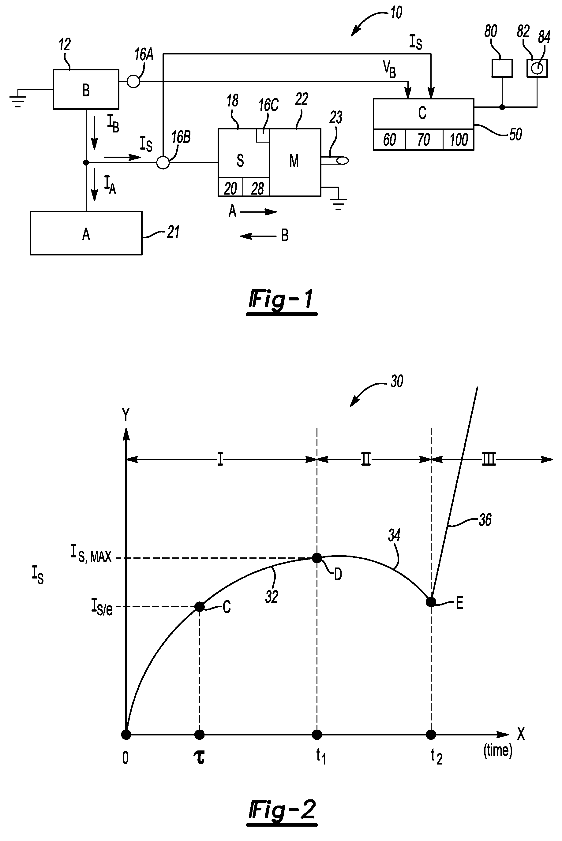
[0016]Referring to the drawings, wherein like reference numbers correspond to like or similar components throughout the several figures, and beginning with FIG. 1, a solenoid monitoring system 10 includes a solenoid device or a solenoid (S) 18 connected to an electric motor (M) 22 or other solenoid-controllable device, e.g., a vehicular starter motor, a motorized valve, a robot, etc. having an output shaft or member 23. Motion of the member 23 can be harnessed as needed to perform any of a variety of useful work. The solenoid 18 is of the electro-mechanical type, and therefore includes one or more wire coils 20 surrounding a moveable piston or plunger 28, with the motion of plunger 28 indicated in FIG. 1 by the arrows A and B. The solenoid 18 can be configured as either a single coil or a dual-coil solenoid as described above without departing from the intended scope of the invention.

[0017]The system 10 includes an electronic control unit or controller (C) 50 and a pair of sensors 1...


PUM


Abstract

A method for monitoring the state of health (SOH) of a solenoid powered by a battery includes measuring a voltage and a current supplied to the solenoid by the battery, using a processor to determine each of an equivalent resistance and inductance of the solenoid using the voltage and the current, comparing the equivalent resistance and the equivalent inductance to a corresponding calibrated threshold, and recording deviations from the corresponding calibrated thresholds as a pair of SOH values. A trend of the SOH values is continuously monitored, and an appropriate control action is taken when either SOH value drops below a calibrated lower limit. A solenoid monitoring system includes a solenoid, voltage and current sensors, and a controller having an algorithm for continuously monitoring a state of health (SOH) of the solenoid as set forth above.

Description

TECHNICAL FIELD[0001]The present invention relates generally to electro-mechanical solenoid devices, and more particularly to a method and an apparatus for continuously monitoring the ongoing state of health of a solenoid device.BACKGROUND OF THE INVENTION[0002]Solenoid devices or solenoids are linear actuator devices having a host of useful applications. For example, solenoids typically serve as a reliable type of on / off switch for precise operational control of various devices, e.g., electrical motors, valves, assembly robots, etc. Solenoids are ordinarily configured as electromechanical devices, although hydraulic and pneumatic variants exist that provide similar utility using different motive forces. A typical solenoid of the electromagnetic variety includes one or more coils of conductive wire surrounding a moveable piston portion or plunger, all of which is positioned within a solid ferromagnetic core. That is, a single-coil solenoid can be used in conjunction with a return sp...

Claims


Application Information

Patent Timeline
Patent Type & Authority Patents(United States)
IPC IPC(8): G01R31/02G06F17/40G01R31/72
CPCG01R31/06G01R31/2829G01R31/72
Inventor RAJAGOPALAN, SATISHSALMAN, MUTASIM A.
Owner GM GLOBAL TECH OPERATIONS LLC
Why Eureka
Try Eureka