
Manufacturing method for motor

a manufacturing method and motor technology, applied in the direction of maintaining head carrier alignment, electric/magnetic/electromagnetic heating, instruments, etc., can solve the problems of increasing the manufacturing cost of such motors, causing reading errors and/or writing errors, and not being suitable for use, so as to reduce the manufacturing cost of the motor. , the effect of reducing the generation of outgas

Inactive Publication Date: 2011-11-15
NIDEC CORP
View PDF14 Cites 6 Cited by
  • Summary
  • Abstract
  • Description
  • Claims
  • Application Information

AI Technical Summary

Benefits of technology

[0013]According to a preferred embodiment of the present manufacturing method, the adhesive of heat curing type will be used in order to affix the sleeve portion and the base portion, which will reduce the manufacturing cost of the motor having such components.
[0014]By virtue of such manufacturing method, the manufacturing cost of the motor will be reduced and the generation of the outgass will be minimized.
[0015]Since the high frequency induction heating is used to heat the area surrounding the hole portion, the heating will be conducted facilitatedly and over heating of the sleeve portion will be minimized. Also, by virtue of such manufacturing method, reliability of the hard disk drive having such spindle motor manufactured in accordance with the present invention will be improved.

Problems solved by technology

Note that reading errors and / or writing errors may be caused in a hard disk drive apparatus in which an inner space thereof is filled with an outgass generated by the adhesive used in the motor.
In general, the anaerobic adhesive and the adhesive of an ultraviolet cure type are more likely to generate the outgass than the adhesive of the heat cure type, and therefore not suitable for use in the hard disk drive which is expected to perform with precision (see Japanese Laid-Open Publication No. 2005-114106).
That is, a large space inside the oven and large size jigs will be required in order to manufacture such motor increasing the manufacturing cost of such motor, and preventing an automation of the manufacture.

Method used


Image

  • Manufacturing method for motor
  • Manufacturing method for motor
  • Manufacturing method for motor

Examples


second preferred embodiment

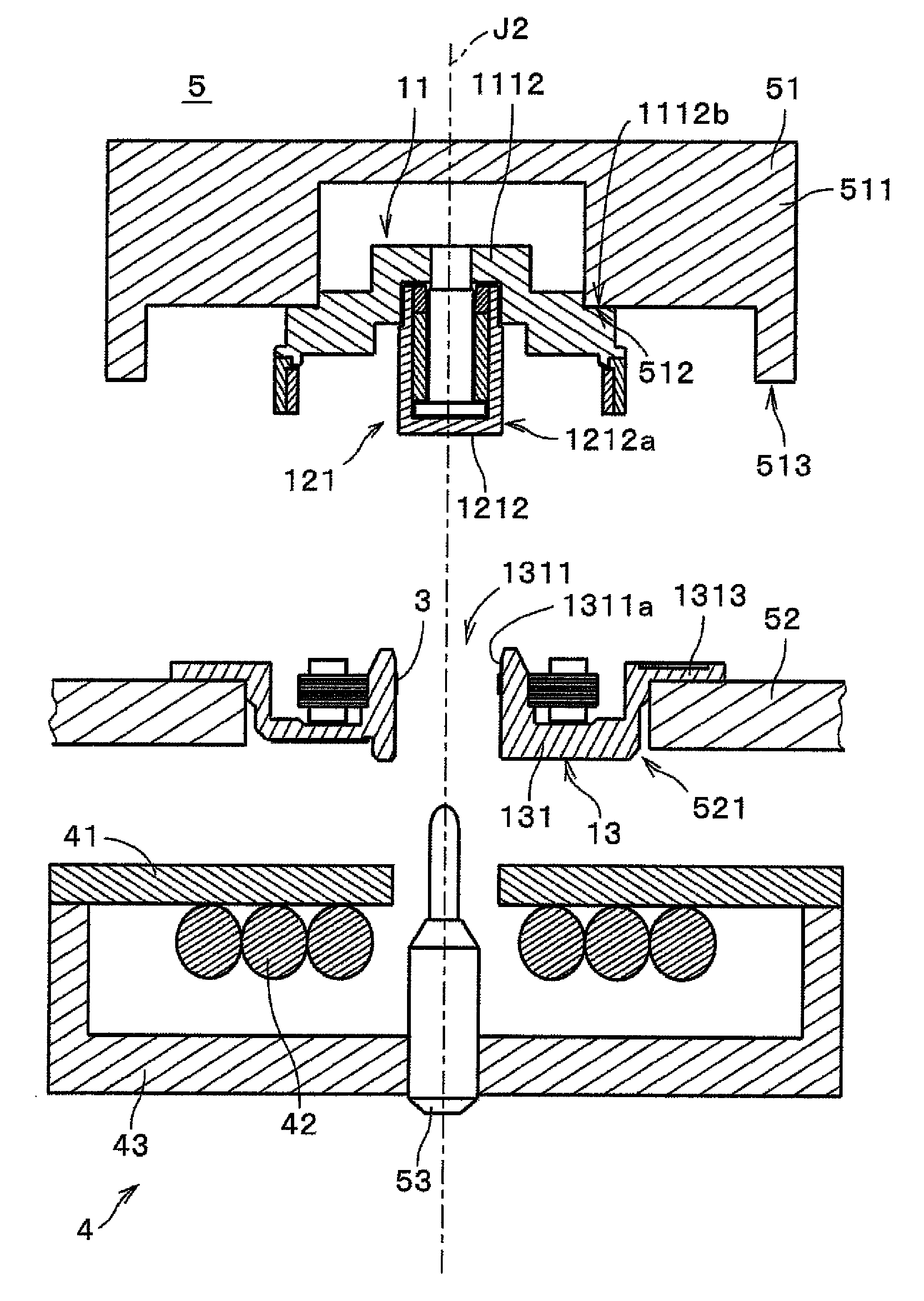
[0082]FIG. 9 is a diagram showing a heating portion used in the initial fixation according to a second preferred embodiment of the present invention. Note that FIG. 9 corresponds to FIG. 5.

[0083]Note that in the description of the second preferred embodiment of the present invention herein, elements similar to those illustrated for the description of the first preferred embodiment of the present invention are denoted by similar reference numerals and descriptions thereof is omitted. Also, note that the manufacturing procedure according to the second preferred embodiment is same as that for the first preferred embodiment except that the initial fixation is conducted by using a heating portion 4a shown in FIG. 9 is used.

[0084]The heating portion 4a shown in FIG. 9 preferably includes a heating tool 46 of a pulse heating type instead of the induction coil 42. A tip portion 461 of the heating tool 46 has a substantially annular shape.

[0085]A portion of the heating tool 46 other than the...


PUM

PropertyMeasurementUnit
cure timeaaaaaaaaaa
temperatureaaaaaaaaaa

Abstract

A sleeve portion is inserted into a hole portion of a base bracket on which an adhesive of heat cure type is applied while a rotor portion and a stator portion are retained by a position determining jig. Then, the sleeve portion is initially affixed to the base bracket by a high frequency induction heating of an induction coil. Then, the initial affixation is cured completely in an oven. Since the adhesive of heat cure type is used, generation of outgass will be minimized and a manufacturing cost of the motor having such components will be reduced.

Description

BACKGROUND OF THE INVENTION[0001]1. Field of the Invention[0002]The present invention relates to a technology for manufacturing a motor and a disk drive apparatus, and more particularly, to a technology for manufacturing a motor in which a sleeve portion into which a shaft will be inserted is affixed via an adhesive to a hole portion arranged at a base portion.[0003]2. Description of the Related Art[0004]Conventionally, an adhesive is used for assembling various components of a spindle motor used for rotating a discoid disk (e.g., storage medium) in a disk drive apparatus such as a hard disk drive, or the like.[0005]For example, according to Japanese Laid-Open Patent Publication No. 2005-114106, a base frame and a bearing sleeve are affixed to one another temporarily by an anaerobic adhesive and then by an ultraviolet thermoset adhesive for a secure connection. By such method, a precise assembly between the base frame and the bearing sleeve is achieved without large scale equipment....

Claims


Application Information

Patent Timeline
Patent Type & Authority Patents(United States)
IPC IPC(8): H02K15/00
CPCG11B19/2009H02K15/12Y10T29/49009Y10T29/49025H02K15/14
Inventor GOMYO, MASATOSEKII, YOICHI
Owner NIDEC CORP
Learn More