Rotating feed distributor

a distributor and rotating technology, applied in the field of cone crushers, can solve the problems of not necessarily crushing to a final uniform size, less saleable end product, and disadvantage, and achieve the effects of reducing wear, reducing power consumption, and improving the performance and efficiency of rock crushers

Active Publication Date: 2011-11-15
SANDVIK SRP
View PDF27 Cites 27 Cited by
  • Summary
  • Abstract
  • Description
  • Claims
  • Application Information

AI Technical Summary

Benefits of technology

[0011]The feed distributor improves both the performance and the efficiency of the rock crusher. The design of the feed distributor also consumes less power, reduces wear, extends maintenance intervals, reduces abuse to the crusher and makes more cubical products when compared to prior art feed distributors. This in turn reduces operating cost / ton of product and increases the yield of sellable product tonnage.

Problems solved by technology

Since rocks fed into the crusher are not always of the same size and shape, they will not necessarily be crushed to a final uniform size.
Such segregation of the rocks is not advantageous as it can lead to a less saleable end product.
However, it has been observed that one of the reasons for inconsistent crushed rock gradation is that the uncrushed rocks are not evenly distributed as they fall into the crusher and instead arrive in the crusher in a segregated fashion.
Consequently, the rocks will not be evenly distributed, which leads to potentially uneven crushing of the rocks.
Rocks outside of a predetermined range will need to be recycled or re-crushed, which is not an efficient process.
Premature wear of the specific parts of prior feed distributors is also a problem.
When rocks fall upon the feed distributor and the chute used in the distributor, the impact tends to wear and erode the feed distributor's components.
The rock crushing environment creates excess and abrasive dust which can also lead to premature wear of certain machine elements, such as bearings.
As a result feed distributor components need to be replaced, which leads to more downtime of the system and, consequently, reduces the efficiency of the overall system.
However, depending upon the environment where it is operated, the device in Sawant may require frequent maintenance.
This is not desirable as the entire rock crushing process must be halted while the rotating feed distributor is attended to.
However, the device in Ryan causes buildup within the device, and, since the device is located within the crusher, is not easily cleaned or serviced.
Furthermore, prior art designs have been observed to comprise drive means that are susceptible to dust and dirt and may unduly slip when driving the feed distributor, such as Gasparac et al., U.S. Pat. No. 3,212,720.

Method used


Image

  • Rotating feed distributor
  • Rotating feed distributor
  • Rotating feed distributor

Examples


Embodiment Construction

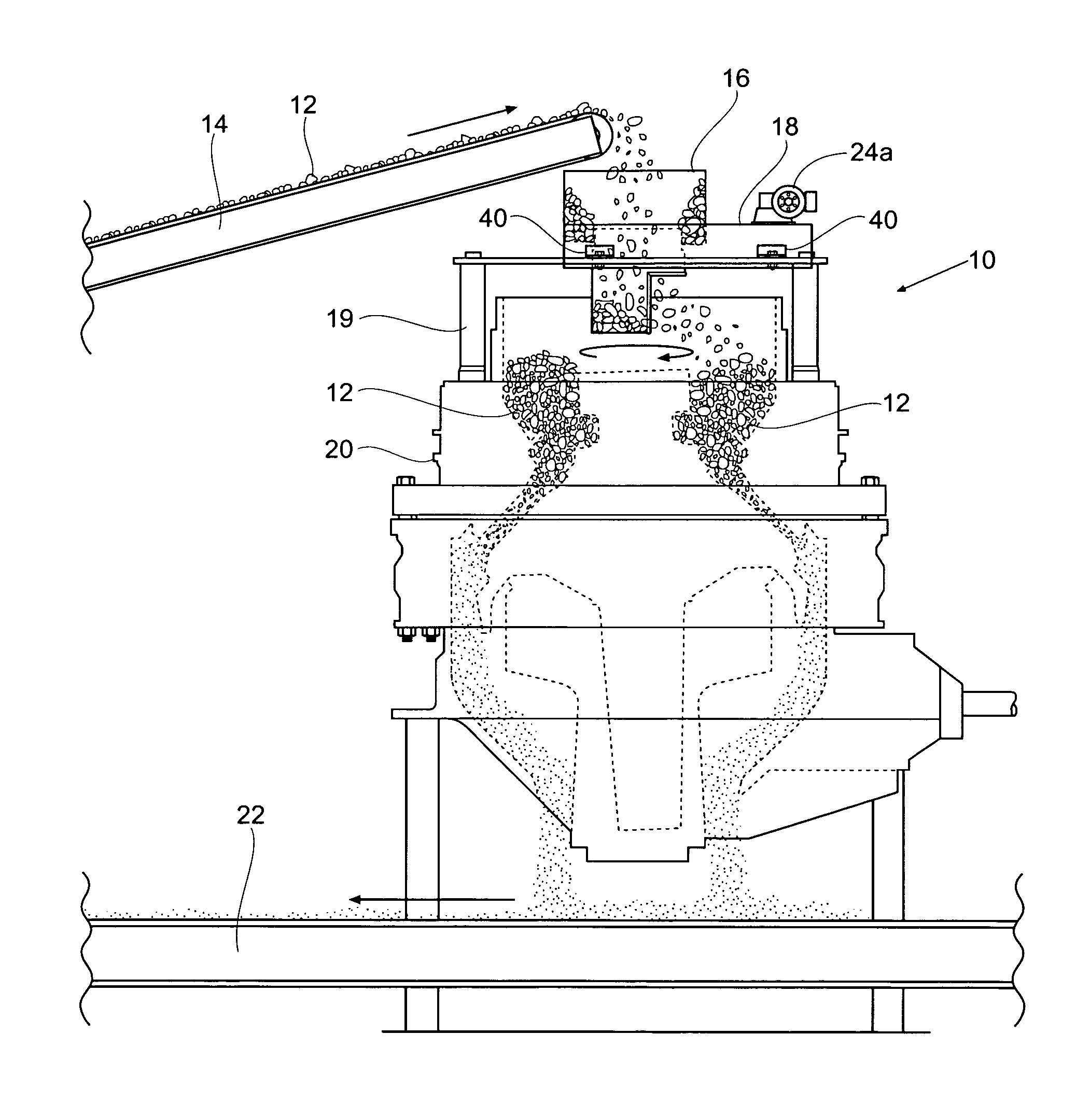
[0020]FIG. 1 shows a side view of a rock crushing system 10 employing the present invention. A plurality of rocks 12 is fed upwards on a conveyor 14. The conveyor 14 delivers the rocks 12 through a feedbox 16 and into an improved feed distributor 18, which is the focus of the present invention. The feed distributor 18 is designed for 360 degree rotation and delivers the rocks 12 uniformly to the crusher 20. The distributor 18 may be mounted to the crusher 20, the conveyor 14, or may be mounted independently. A frame or mount 19 holds the feed distributor 18 in place over the crusher 20. The frame 19 can encompass a wide range of shapes and sizes that will adequately mount the distributor 18 over the crusher 20. The feedbox 16 should be considered a stand-alone feature that is not part of the present invention. The feed distributor 18 passes the rocks 12 into the crusher 20, which rotates or gyrates and crushes the rocks 12. The crushed rocks 12 exit below the crusher 20, possibly on...


PUM


Abstract

A rotating feed distributor for use in connection with rock crushers and other devices. The feed distributor comprises a platform for receiving rocks and a chute having an inlet and outlet wherein the rocks pass through. The feed distributor is designed to reduce wear by evenly distributing rocks into the crusher. The chute is supported and rotated utilizing a motor, drive belts, a sheave structure, thrust bearings and idler wheels. The sheave structure includes a flange and a face which are generally orthogonal to one another. The belts, thrust bearings and idler wheels each engage with the sheave structure.

Description

BACKGROUND OF THE INVENTION[0001]This invention relates to cone crushers used for crushing rocks and, more specifically, feed distributors used in combination with rock crushers and other devices.[0002]Generally, a belt conveyor or feeder delivers rocks and stones into a crusher. The rocks will ride up the conveyor, whose end is located above the input of the crusher. The rocks are dumped under the force of gravity into the crusher, which will then break the rocks into a predetermined size. Preferably, the uncrushed rocks will first pass through a feed distributor, which will assist in dispersing the uncrushed rocks into the crusher.[0003]Since rocks fed into the crusher are not always of the same size and shape, they will not necessarily be crushed to a final uniform size. However, it is preferable to have the crushed rocks be within a relative range and size; otherwise the rocks and stones need to be recrushed. Furthermore, the final crushed rock product should preferably have a u...

Claims


Application Information

Patent Timeline
Patent Type & Authority Patents(United States)
IPC IPC(8): B02C19/00
CPCB02C23/02B02C2/007
Inventor SAWANT, ULHAS S.SHERIDAN, JAMES A.
Owner SANDVIK SRP
Why Eureka
Try Eureka