
LED drivers and driver controllers

Active Publication Date: 2011-11-15
SPECTRUM ILLUMINATION
View PDF3 Cites 30 Cited by
  • Summary
  • Abstract
  • Description
  • Claims
  • Application Information

AI Technical Summary

Benefits of technology

[0008]The present invention provides both improved LED drivers and improved LED driver controls that address the drawbacks discussed above, as well as other disadvantages of prior LED drivers and LED driver controllers. The improved LED drivers of the present invention offer fast response times, extra illumination, and stabilized outputs. The improved LED driver controllers of the present invention offer easy methods and systems for configuring and controlling multiple LED drivers.
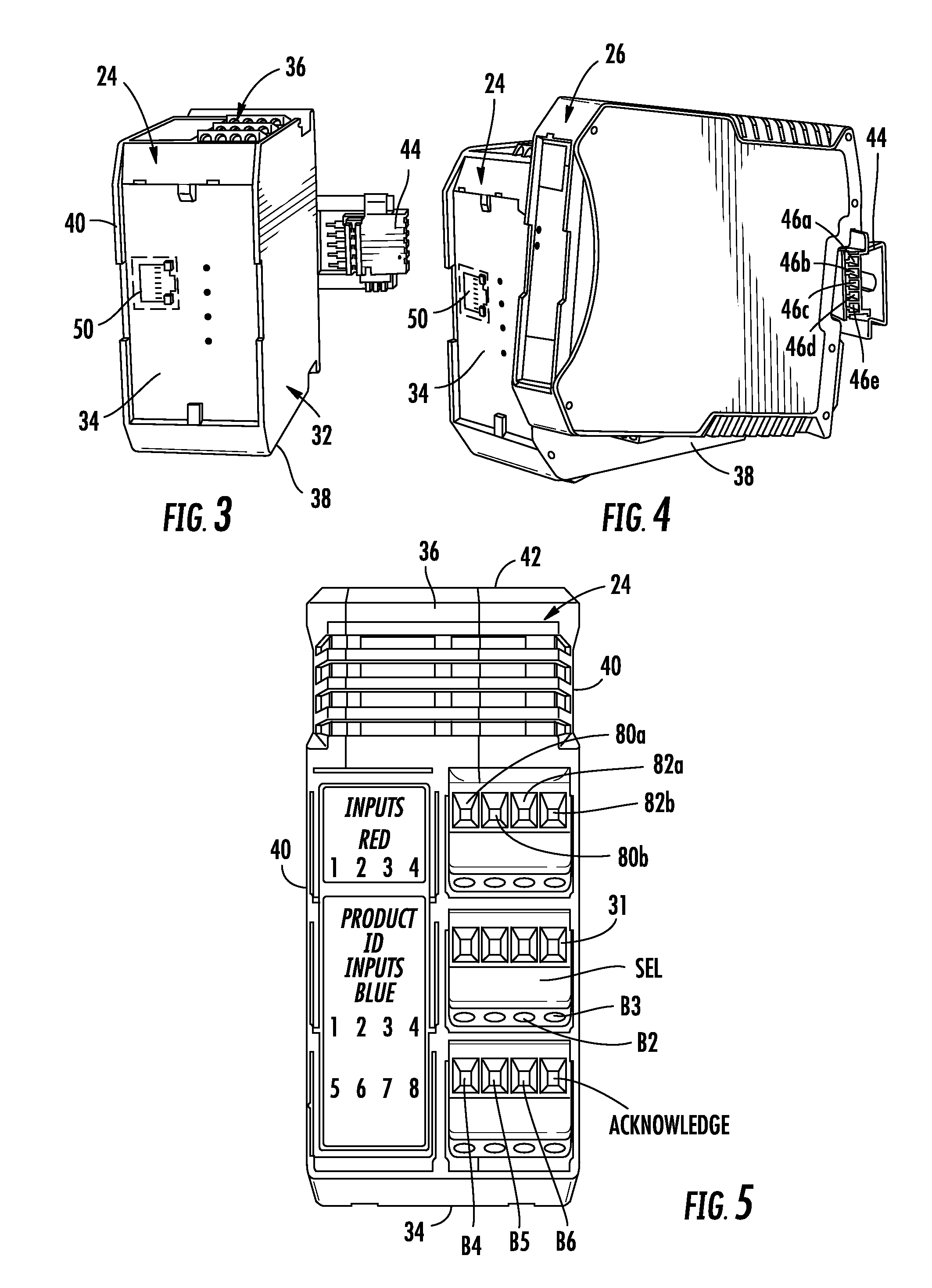
[0009]According to one aspect of the present invention, an LED control unit for controlling at least one LED driver is provided. The control unit includes a housing, an input, a first output, a controller, and a network port, such as, but not necessarily limited to, an Ethernet port. The input is adapted to receive a timing signal that includes a detectable voltage transition. The first output is adapted to output a first control signal for controlling a first LED driver. The controller is adapted to allow a first delay to be programmed into it whereby, when the controller detects the voltage transition in the timing signal, the controller outputs the first control signal after waiting for a time period equal to the first delay. The network port is electrically coupled to the controller and allows a personal computer to be operably coupled to the network port so that the personal computer can be used to program the time of the first delay into the controller.
[0014]In summary, the various LED drivers and driver control units of the present invention provide an improved method and system for controlling high intensity LEDs, offering easy-to-use control features, reliable operation, adjustability, easy set-up, and fast response times. These and other benefits of the present invention will be apparent to one skilled in the art in light of the following description and the accompanying drawings.

Problems solved by technology

Existing drivers for high-intensity LEDs, however, have suffered from several drawbacks.
In some instances, the drivers powering the LEDs may not be able to turn the LEDs on in as fast as a time as would be desirable.
In other instances, the current supplied to the LEDs by the driver does not stabilize for an undesirably long amount of time, thereby causing the illumination provided by the LEDs to fluctuate for the same amount of time.
Still further, in other situations it is not easy to set up and control the LED drivers in the particular ways demanded for a particular application.

Method used


Image

  • LED drivers and driver controllers
  • LED drivers and driver controllers
  • LED drivers and driver controllers

Examples


Embodiment Construction

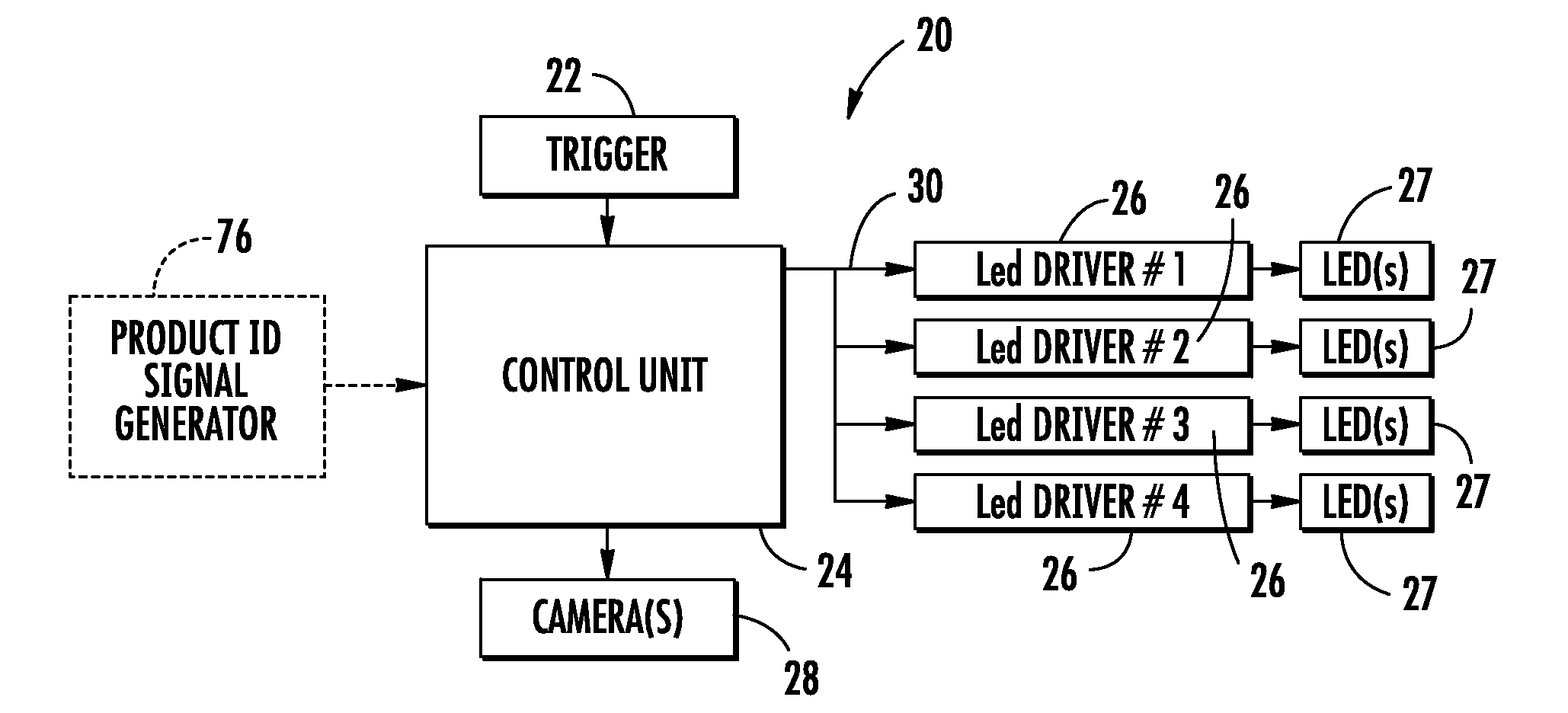
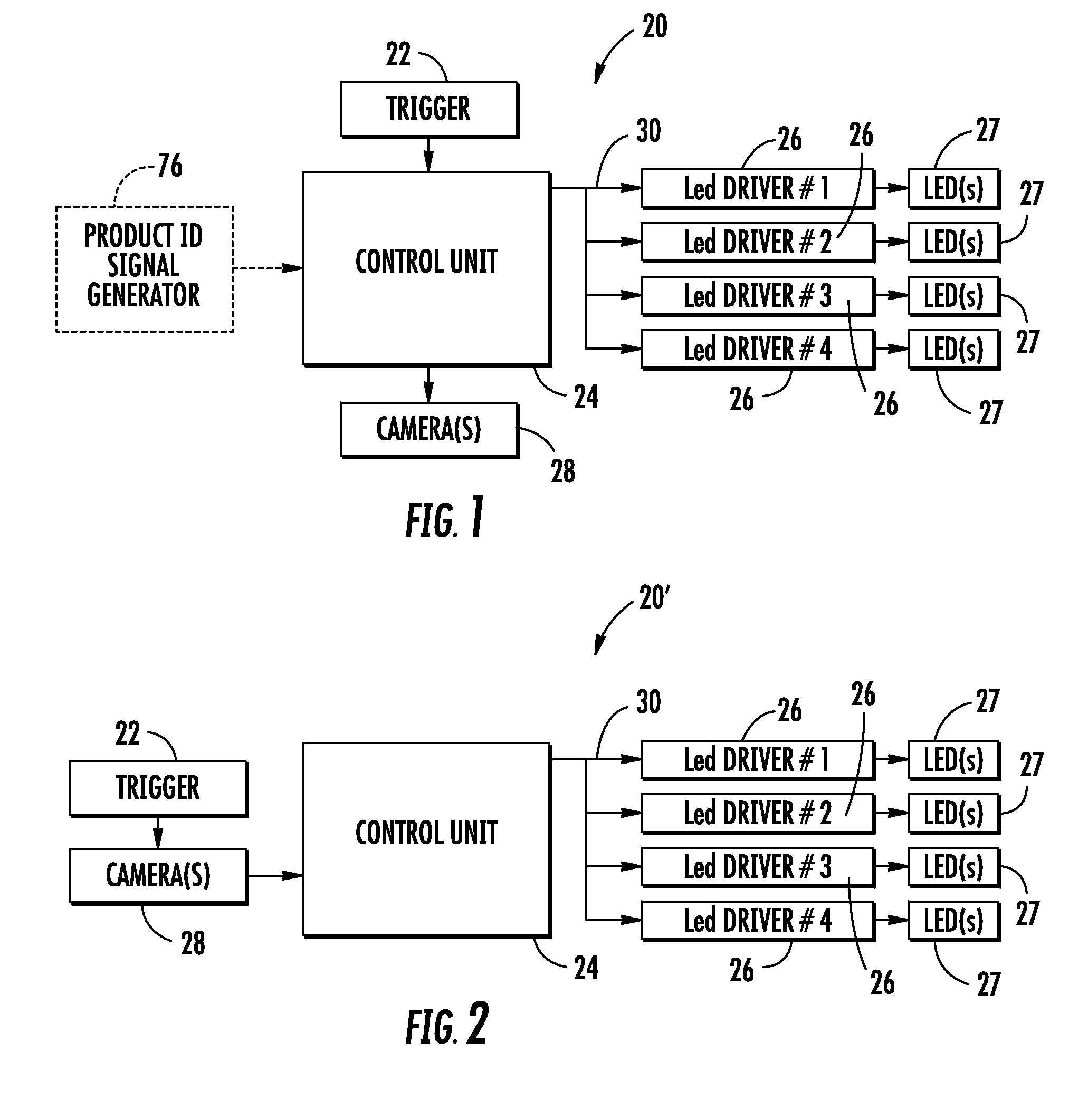
[0037]The present invention will now be described in more detail wherein the reference numerals appearing in the following written description correspond to like-numbered elements in the accompanying drawings. An LED control system 20 according to a first aspect of the present invention is depicted in block diagram form in FIG. 1. LED control system 20 includes a trigger 22, a control unit 24, a plurality of LED drivers 26 (four are illustrated in FIG. 1, although more or less can be used in accordance with the present invention), one or more cameras 28, and a bus 30 electrically coupling the control unit 24 to the plurality of LED drivers 26. The LED control system 20 depicted in FIG. 1 is used to control the illumination of one or more LEDs 27 attached to each of the LED drivers 26. Typically, when the LEDs 27 are being used to provide illumination for one or more cameras, it may be desirable to flash or strobe the LEDs 27 on and off so that, between pictures, the LEDs 27 are not ...


PUM


Abstract

LED drivers and LED driver controllers are disclosed for controlling one or more high-intensity LEDs. The LED driver controllers may control one or more LED drivers in multiple different ways, including controlling on times, off times, delays, current levels, and other parameters. The LED drivers may have fast response times in which the LEDs are illuminated within microseconds after receiving a control signal. The LED drivers may also include other features, including a current boost for temporarily illuminating the LEDs at levels exceeding their maximum continuous current rating, as well as brightness controls for the LEDs, and other features. The LED drivers and / or LED driver controllers may be especially suitable for LEDs used to provide lighting for high-speed visions systems.

Description

CROSS-REFERENCE TO RELATED APPLICATIONS[0001]This application claims priority to U.S. provisional application Ser. No. 60 / 940,981, filed May 31, 2007 by David J. Hardy entitled LED DRIVER AND DRIVER CONTROLLER, the complete disclosure of which is incorporated by reference herein.BACKGROUND OF THE INVENTION[0002]The present invention relates generally to high intensity light emitting diodes (LEDs), and more particularly to the drivers and driver controllers used for illuminating the LEDs.[0003]High intensity LEDs are commonly used in industrial settings for supplying illumination to high-speed camera equipment that takes pictures of products. In such settings, it is common for an automated camera to take pictures of the products being manufactured or assembled, often as the product passes by one or more particular points on an assembly line. Such pictures are often analyzed by a computer to determine if there are any defects in the product.[0004]For example, in a bottling plant, a ca...

Claims


Application Information

Patent Timeline
IPC IPC(8): H05B37/02
CPCH05B33/0842H05B45/30H05B45/345H05B45/375H05B45/38
Inventor HARDY, DAVID J.
Owner SPECTRUM ILLUMINATION
Learn More