Masking device, lithographic apparatus, and device manufacturing method

a technology of lithographic projection apparatus and masking device, which is applied in the direction of electrical apparatus, printers, instruments, etc., can solve the problems of inability to satisfactorily move high moving mass at high scanning speed without conventional motors, and achieve the effect of effective masking function, lower mass, and high scanning acceleration and scanning speed

Active Publication Date: 2011-11-15
ASML NETHERLANDS BV
View PDF32 Cites 9 Cited by
  • Summary
  • Abstract
  • Description
  • Claims
  • Application Information

AI Technical Summary

Benefits of technology

[0020]Such an arrangement provides an advantage in that the first and second masking structures are isolated from one another while providing an effective masking function. A further advantage being that vibrations and disturbances from the first masking structure and the apparatus frame do not disturb the second masking structure, and vice versa. The uncoupled masking structure have a lower mass than the coupled masking structure. Thus, lower driving forces are required to move the masking structure enabling higher accelerations and scanning speeds to be achieved.
[0022]This arrangement provides the advantage in that the cooling of the first masking structure enables the dimension of a first set of blades of the masking structure in the direction of the projection beam (the thickness) to be reduced in comparison with conventional blades. The thinner first set of blades takes up less room in the region of the focal plane than conventional blades enabling a second set of blades to also be disposed within proximity of the focal plane, yet still provide good masking with sharp edges.

Problems solved by technology

For example, problems arise when the masking devices are arranged to scan the mask.
As higher scanning speeds are demanded, conventional masking devices fail.
Further, the high moving mass cannot be satisfactorily moved at high enough scanning speeds by conventional motors without causing disturbances to be transferred to other parts of the apparatus.

Method used


Image

  • Masking device, lithographic apparatus, and device manufacturing method
  • Masking device, lithographic apparatus, and device manufacturing method
  • Masking device, lithographic apparatus, and device manufacturing method

Examples


Embodiment Construction

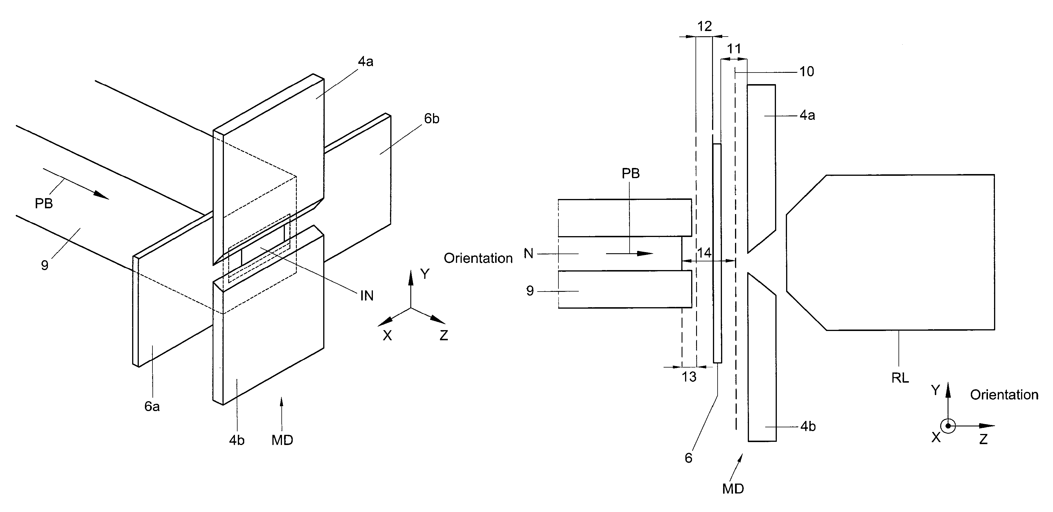
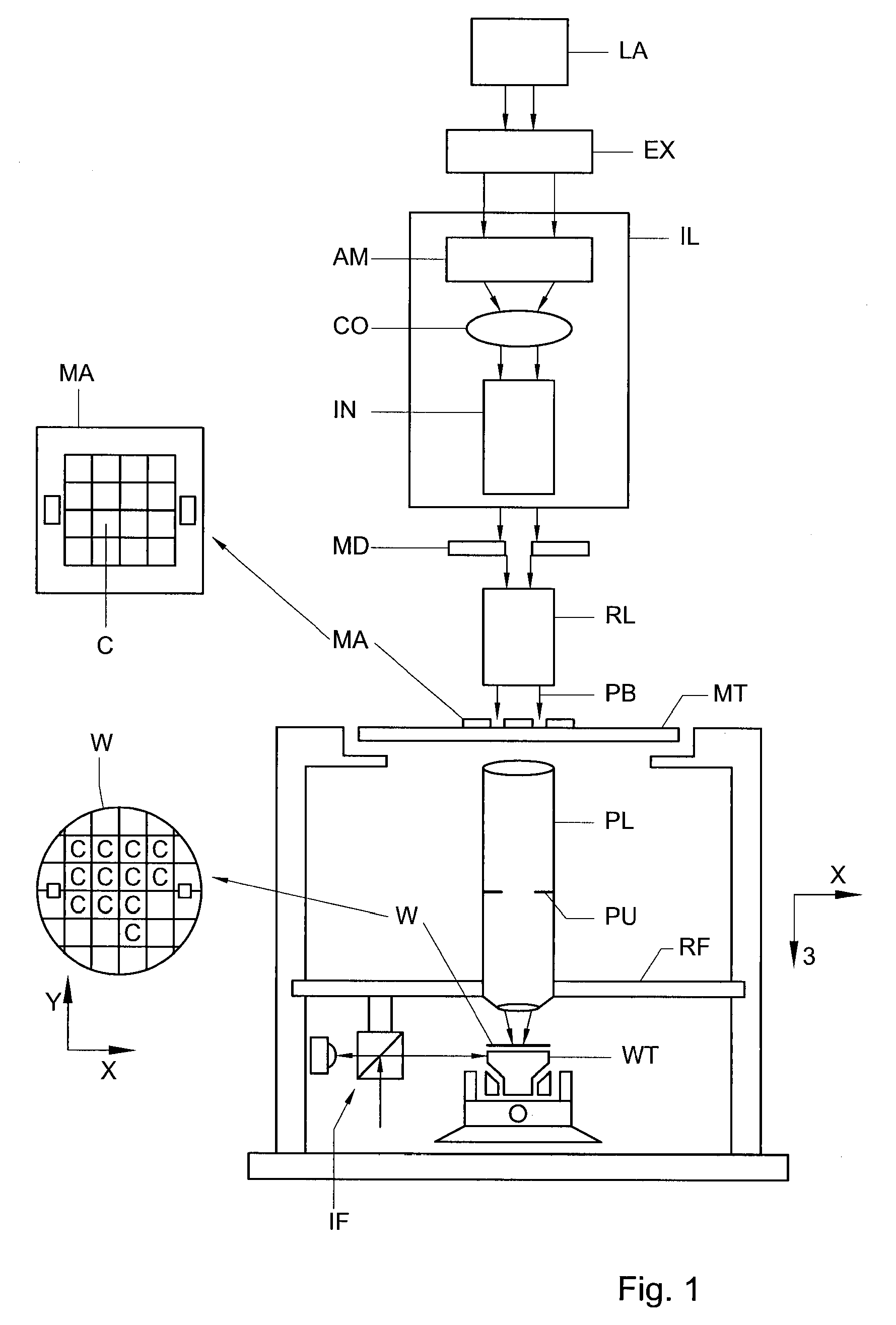
[0039]FIG. 1 schematically depicts a lithographic projection apparatus according to a particular embodiment of the invention. The apparatus comprises:[0040]a radiation system Ex, IL: for supplying a projection beam PB of radiation (e.g. UV radiation). In this particular case, the radiation system also comprises a radiation source LA;[0041]a masking device MD: provided for selectively shielding parts of a mask MA (eg. a reticle) from the projection beam, in other embodiments, masking device may be provided to selectively shield parts of the patterned projection beam;[0042]relay optics RL: provided for projecting the radiation that passes through the masking device to the mask MA;[0043].a first object table (mask table / holder) MT: provided with a mask holder for holding the mask MA, and connected to first positioning mechanism for accurately positioning the mask with respect to item PL;[0044].a projection system (“lens”) PL: (e.g. a projection lens) for imaging an irradiated portion o...


PUM

PropertyMeasurementUnit
thicknessaaaaaaaaaa
distanceaaaaaaaaaa
wavelengthaaaaaaaaaa

Abstract

A lithographic projection apparatus having a masking device for obscuring part of at least one of a patterning device used for patterning a projection beam before imaging the patterned beam onto a substrate. The masking device includes a first masking structure to obscure said part of said patterning device in a first direction and a second masking structure to obscure said part in a second different direction, wherein said first and second masking structure are disposed in the vicinity of said focal plane in a mechanically uncoupled arrangement with respect to each other.

Description

PRIORITY INFORMATION[0001]This application claims priority from European Patent Application No. 03076673.7, filed May 30, 2003, herein incorporated by reference in its entirety.BACKGROUND OF THE INVENTION[0002]1. Field of the Invention[0003]The present invention relates to a masking device, a related lithographic projection apparatus, and a device manufacturing method.[0004]2. Description of the Related Art[0005]Lithographic apparatus can be used, for example, in the manufacture of integrated circuits (ICs). In such a case, a patterning device may be used to generate a desired circuit pattern corresponding to an individual layer of the IC, and this pattern can be imaged onto a target portion (e.g. comprising one or more dies) on a substrate (silicon wafer) that has been coated with a layer of radiation-sensitive material (resist).[0006]The term “patterning device” as here employed should be broadly interpreted as referring to a device that can be used to impart an incoming radiation...

Claims


Application Information

Patent Timeline
Patent Type & Authority Patents(United States)
IPC IPC(8): G03B27/72H01L21/027G03F7/20
CPCG03F7/70066G03F7/70858G03F7/20
Inventor VERWEIJ, ANTOINE HENDRIKMOLENAAR, JACOBUS FREDERIKVAN DEN HOVEN, GERBRAND PETRUS JOHANNESVERVOORDELDONK, MICHAEL JOHANNESPARDOEL, MICHEL GERARDUSVERDOES, GERARDUS JOHANNESVAN EIJK, JAN
Owner ASML NETHERLANDS BV
Why Eureka
Try Eureka