
Power conversion device and control method thereof

a power conversion device and control method technology, applied in the direction of electric variable regulation, process and machine control, instruments, etc., can solve the problems of reducing increasing the power dissipation, so as to reduce the switching times of the active switch elements, enhance the conversion efficiency of the power conversion device, and reduce the effect of power dissipation

Active Publication Date: 2011-11-15
IND TECH RES INST
View PDF5 Cites 34 Cited by
  • Summary
  • Abstract
  • Description
  • Claims
  • Application Information

AI Technical Summary

Benefits of technology

[0006]Embodiments of a power conversion device and a control method thereof are provided, wherein a control signal having substantially the same frequency as an alternating-current (AC) voltage is utilized to convert a direct-current (DC) voltage to an alternating current corresponding to the AC voltage. Thus, the switching times of the active switch elements can be decreased, and the power dissipation can be reduced. Therefore, the conversion efficiency of the power conversion device can be enhanced.

Problems solved by technology

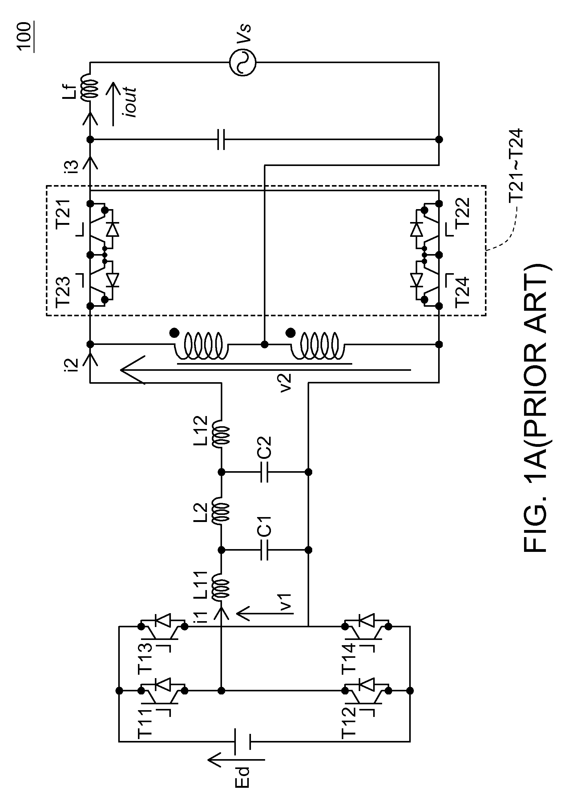
However, under the control of the control signal with relatively high frequency, the active switch elements T21 to T24 are switched on and off frequently, thus increase the power dissipation and decrease the conversion efficiency of the power conversion device 100.

Method used


Image

  • Power conversion device and control method thereof
  • Power conversion device and control method thereof
  • Power conversion device and control method thereof

Examples


Embodiment Construction

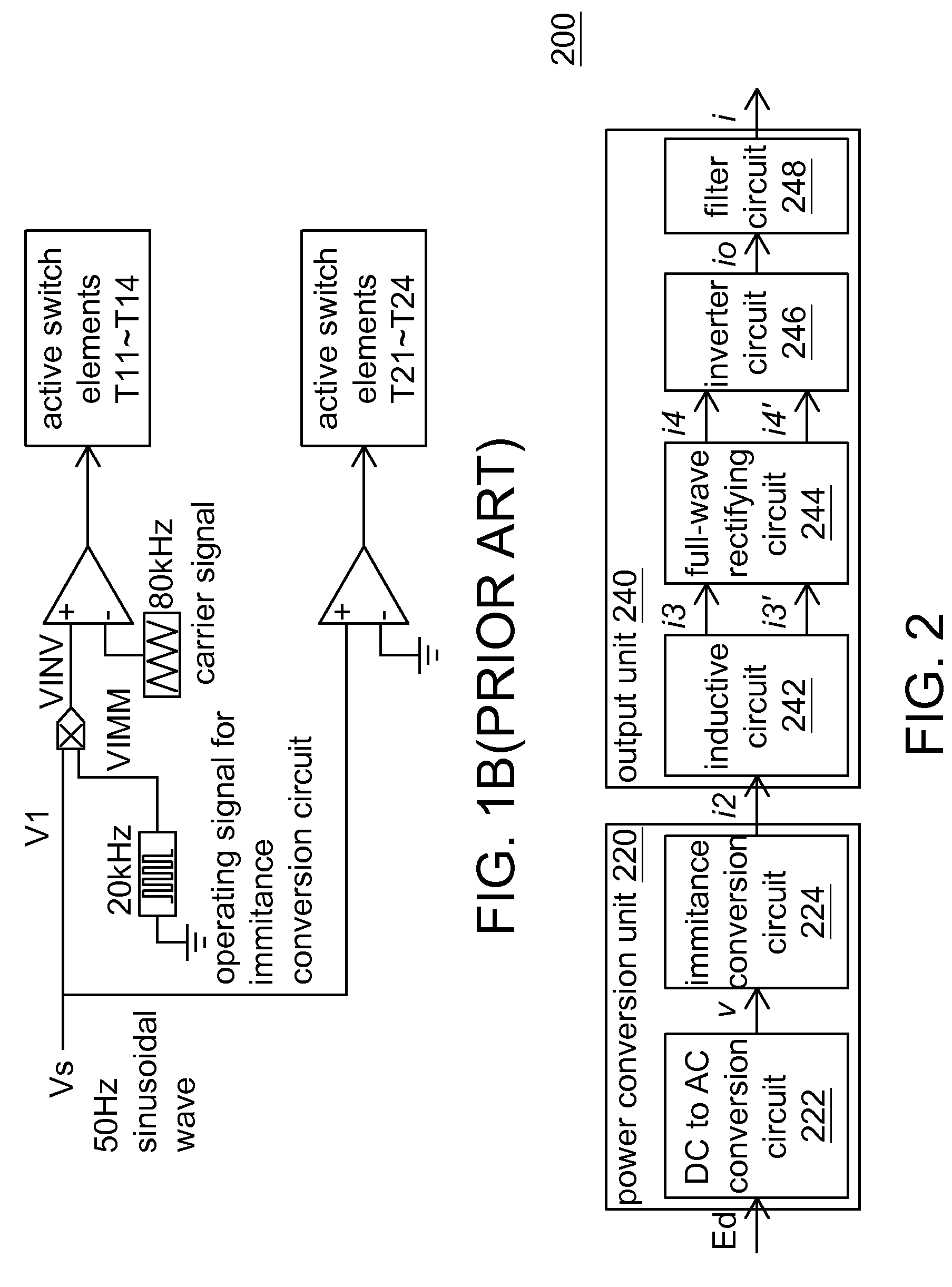
[0020]An embodiment of the application provides a power conversion device for converting a direct current (DC) voltage to an alternating current corresponding to an alternating current (AC) voltage according to the AC voltage. The power conversion device of the embodiment can be connected in parallel to a power grid providing the AC voltage, so as to be applied in a photo-voltaic (PV) power system. The AC voltage mentioned above is, for example, the grid voltage. The alternating current corresponds to the AC voltage means that the alternating current provided by the power conversion device of the embodiment can be substantially synchronous with the AC voltage. An exemplary power conversion device will be made below as an example for elaborating the power conversion device and the control method thereof disclosed in the embodiments.

[0021]FIG. 2 is a block diagram showing a power conversion device 200 according to an exemplary embodiment. The power conversion device 200 includes a pow...


PUM


Abstract

A power conversion device is provided for converting a DC voltage to an alternating current corresponding to an AC voltage according to the AC voltage, which includes a power conversion unit and an output unit. The power conversion unit converts the DC voltage to a high-frequency current having two envelops corresponding to the waveform of the AC voltage. The output unit includes an inductive circuit, a full-wave rectifying circuit, an inverter circuit and a filter circuit. The inductive circuit provides two induced currents according to the high-frequency current, wherein one induced current and the high-frequency current are in phase, and the other induced current and the high-frequency current are in antiphase. The full-wave rectifying circuit full-wave rectifies the two induced currents. The inverter circuit alternatively transfers the two full-wave rectified induced currents, and thus output an output current. The filter circuit filters the output current to provide the alternating current.

Description

[0001]This application claims the benefit of Taiwan application Serial No. 97147735, filed Dec. 8, 2008, the subject matter of which is incorporated herein by reference.TECHNICAL FIELD[0002]The invention relates in general to a power conversion device and a control method thereof, and more particularly to a power conversion device which converts a direct-current voltage to an alternating current corresponding to an alternating-current voltage according to the alternating-current voltage and a control method thereof.BACKGROUND[0003]As the technology develops, people have been gradually placed importance on how to convert green energy into usable power for human beings. There are many green energy conversion device have been provided in the market, and one of them is a power conversion device applied in a photo-voltaic (PV) power system. Such a power conversion device can be referred to as a PV inverter.[0004]Refer to both of the FIGS. 1A and 1B. FIG. 1A is a circuit diagram showing a...

Claims


Application Information

Patent Timeline
Patent Type & Authority Patents(United States)
IPC IPC(8): H02M7/5387H02M7/5395
CPCH02M7/4807
Inventor HUANG, YUNG-FUKONISHI, YOSHIHIRO
Owner IND TECH RES INST
Learn More