Single-input control circuit for programming electronic ballast parameters
a control circuit and single-input technology, applied in the field of single-input control circuits for programming electronic ballast parameters, can solve the problems of increasing the expected life of the lamp, increasing the erosion of the electrode, and fewer lamp starts before failure, so as to reduce the size of the ic footprint and more compact fluorescent lighting configurations and applications
- Summary
- Abstract
- Description
- Claims
- Application Information
AI Technical Summary
Benefits of technology
Problems solved by technology
Method used
Image
Examples
first embodiment
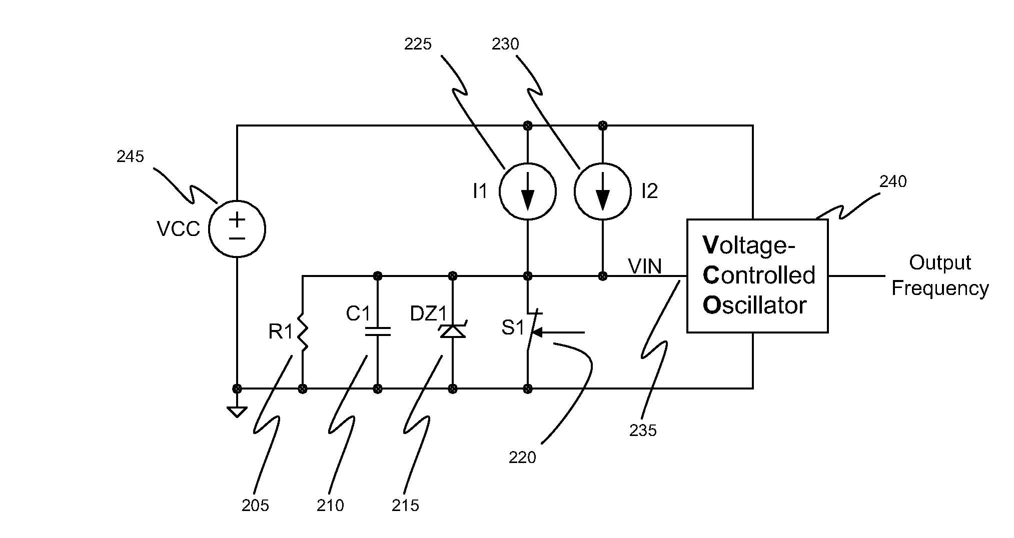
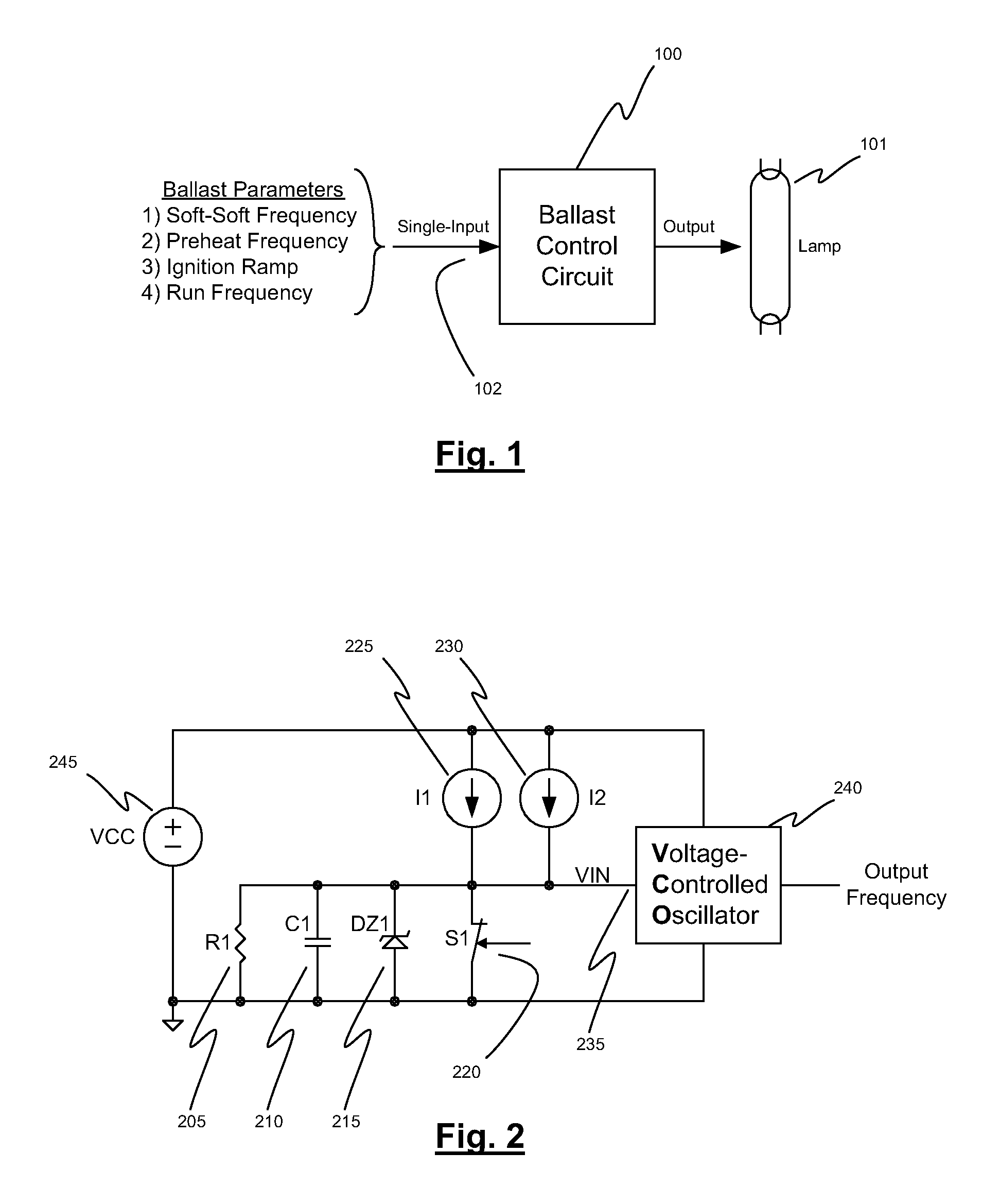
[0029]In this first embodiment, resistor R1205 and capacitor C1210 program the ballast soft-start and ignition ramp times; first current source I1225 and resistor R1205 program the ballast preheat frequency; and second current source I2230 and zener diode DZ1215 program the ballast run frequency.
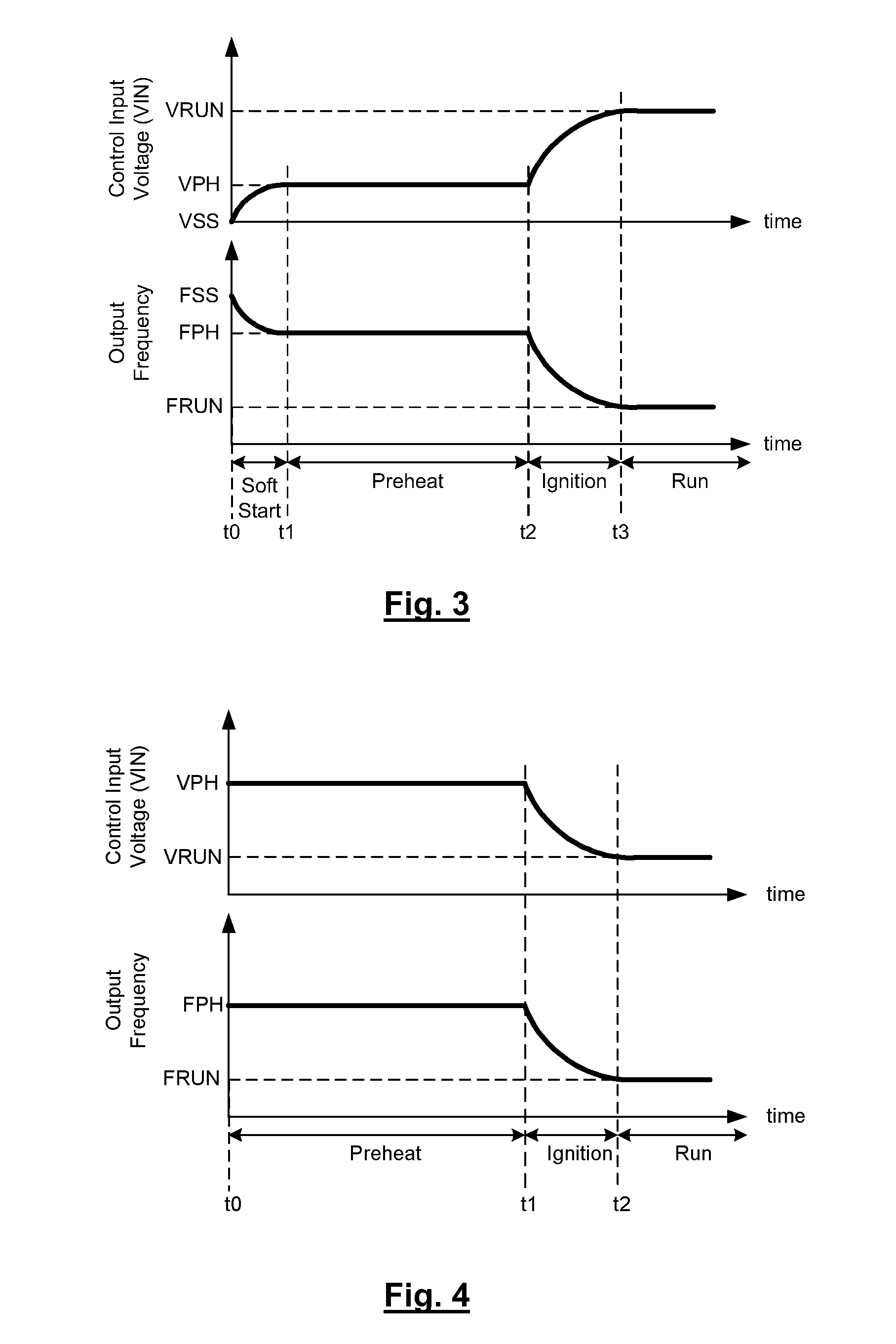
[0030]In a modification of the first embodiment, the output frequency of oscillator VCO 240 increases as the input voltage VIN increases. Current sources I1225 and 12230 are initially enabled on this modified embodiment. This will cause VIN to start at a higher voltage level set by the zener diode DZ1215. Current source I2230 is then disabled after the preheat time has ended and the control voltage VIN will ramp down to the final run level set by current source I1225 and resistor R1205. In this modified configuration, switch S1205 is not needed, but the soft-start feature at initial start up no longer exists. FIG. 4 illustrates a frequency response for such a configuration using a voltage co...
second embodiment
[0032]As shown by FIG. 5, the present invention includes an input supply voltage VCC 500, two resistors R1505 and R2510, a capacitor C1515, a current source 11520, and a switch S1525. The two resistors R1505 and R2510 are connected in series to form a standard voltage divider network between VCC 500 and COM. The node formed between the two resistors is the control input voltage node 530. Capacitor C1515 is then placed from control input voltage node 530 to COM. Current source I1520 is connected to control input voltage node 530 such that current is sourced into control input voltage node 530. Finally, switch S1525 is connected from the control input voltage node 530 to COM. Control input voltage node 530 is then connected to the input of a voltage-controlled oscillator VCO 535 that generates an output frequency for controlling the operating frequency of the electronic ballast.
[0033]FIG. 6 illustrates a frequency timing diagram of the frequency response to the oscillator control inpu...
third embodiment
[0038]As shown by FIG. 8, the present invention includes a single programming resistor R1705, a current source I1710, and a look-up table circuit 715. Look-up table circuit 715 can be any circuit known in the art that is capable of providing look-up table functionality, including an IC. Current source I1710 flows through the resistor 705 to produce a voltage VIN across the resistor. Immediately after the supply voltage to look-up table circuit 715 is powered on, current source I1710 is maintained such that VIN is stabilized at a voltage level required for the particular lamp. The stabilized voltage level VIN is then read by look-up table circuit 715 to determine the ballast parameters, and the ballast parameters are locked in place, all before the ballast starts. It is preferable to take an accurate reading prior to powering on the complete look-up table circuit to avoid noise and other power fluctuations across resistor R1705 and at input node 720. Input node 720 to look-up table c...
PUM
 Abstract
Description
Claims
Application Information
 - R&D
- Intellectual Property
- Life Sciences
- Materials
- Tech Scout
- Unparalleled Data Quality
- Higher Quality Content
- 60% Fewer Hallucinations
Browse by: Latest US Patents, China's latest patents, Technical Efficacy Thesaurus, Application Domain, Technology Topic, Popular Technical Reports.
© 2025 PatSnap. All rights reserved.Legal|Privacy policy|Modern Slavery Act Transparency Statement|Sitemap|About US| Contact US: help@patsnap.com


