Phase locked loop

a phase lock and loop technology, applied in the direction of pulse automatic control, electrical equipment, etc., can solve the problem of requiring a larger chip area for the effect of capacitan

Inactive Publication Date: 2011-11-22
MEDIATEK INC
View PDF6 Cites 33 Cited by
  • Summary
  • Abstract
  • Description
  • Claims
  • Application Information

AI Technical Summary

Benefits of technology

[0002]The invention relates to phase locked loops (PLLs), and more particularly, to a phase locked loop capable of improving stability without greatly increasing chip area thereof.

Problems solved by technology

However, a larger capacitance requires a larger chip area.

Method used


Image

  • Phase locked loop
  • Phase locked loop
  • Phase locked loop

Examples


Embodiment Construction

[0012]The following description is of the best-contemplated mode of carrying out the invention. This description is made for the purpose of illustrating the general principles of the invention and should not be taken in a limiting sense. The scope of the invention is best determined by reference to the appended claims.

[0013]Certain terms are used throughout the description and claims to refer to particular system components. As one skilled in the art will appreciate, consumer electronic equipment manufacturers may refer to a component by different names. This document does not intend to distinguish between components that differ in name but not function.

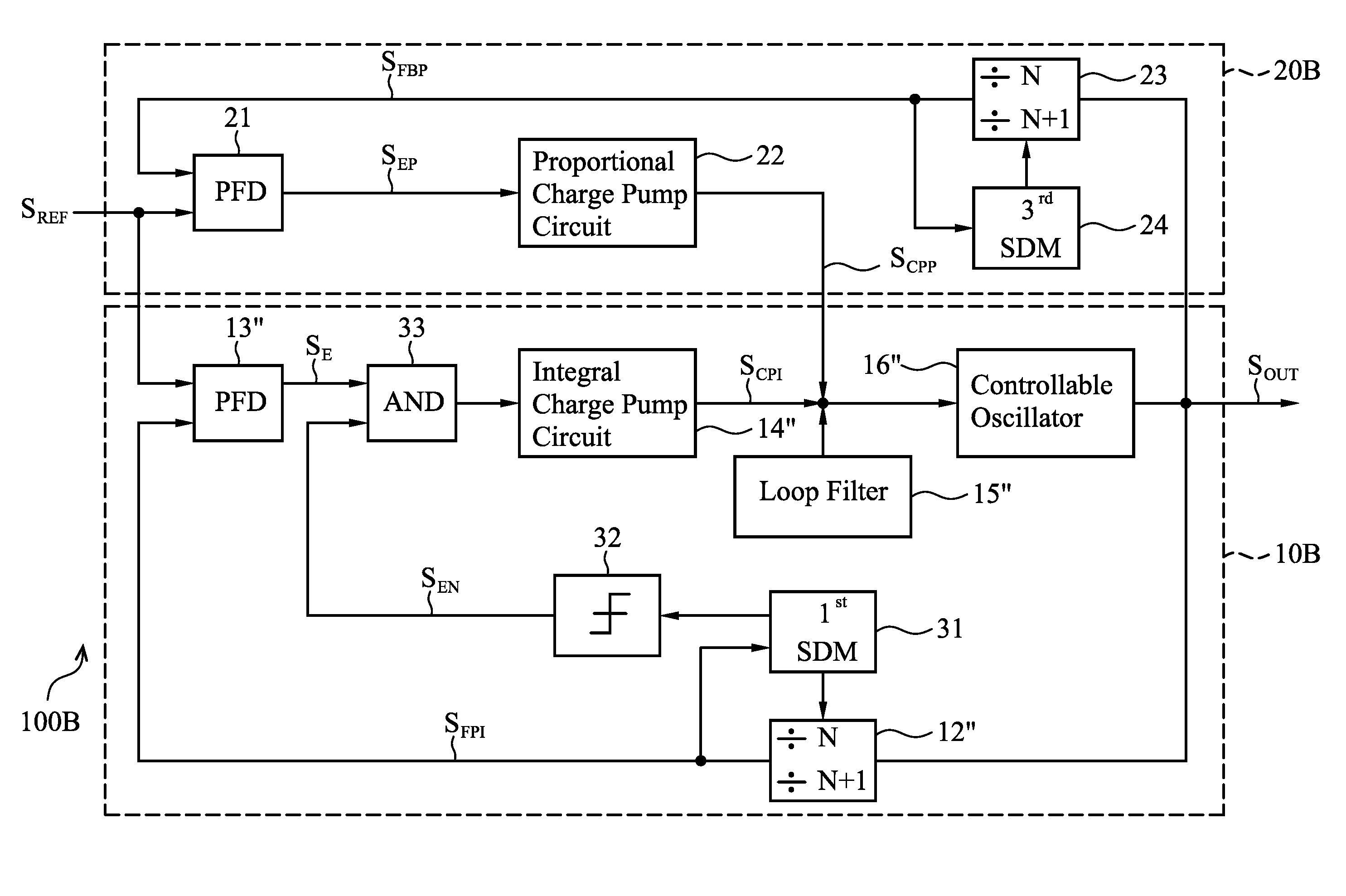
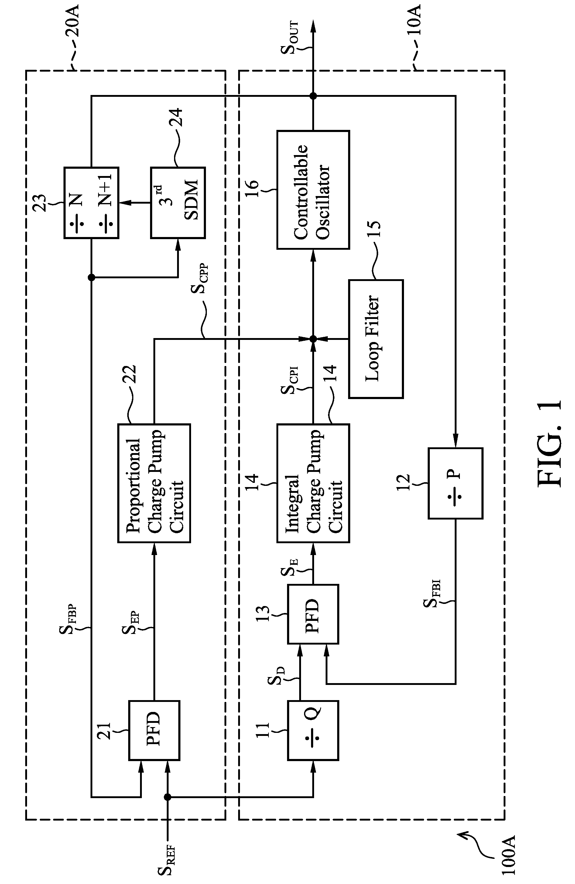
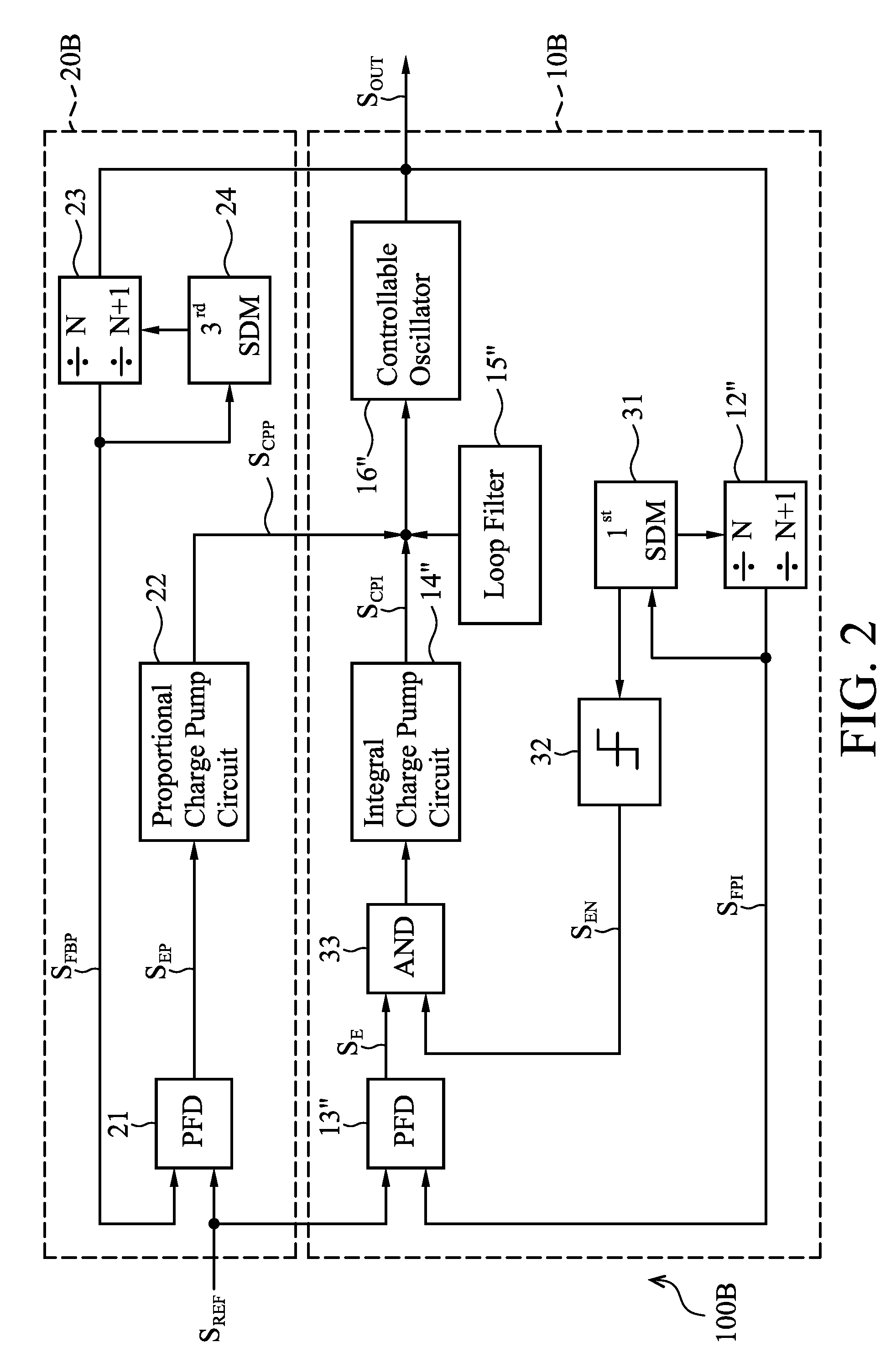
[0014]In order to improve stability for phase locked loops (PLLs), embodiments of the invention increase equivalent capacitance of PLLs by decreasing an update ratio and / or update times of a control signal for a controllable oscillator therein. FIG. 1 shows an embodiment of a phase locked loop according to the invention. As shown, th...


PUM


Abstract

Phase locked loop circuits capable of increasing an equivalent capacitance thereof to improve stability are provided, in which an integral part comprises a first phase frequency detector providing a phase error signal, a first charge pump circuit generating a control signal according to the phase error signal, a controllable oscillator providing an output clock according to the control signal, and a sampling adjustment unit decreasing the number of times the control signal is updated according to the phase error signal. A proportional part is coupled between the controllable oscillator and a reference clock and operated in a fraction mode.

Description

BACKGROUND OF THE INVENTION[0001]1. Field of the Invention[0002]The invention relates to phase locked loops (PLLs), and more particularly, to a phase locked loop capable of improving stability without greatly increasing chip area thereof.[0003]2. Description of the Related Art[0004]Many different types of integrated circuits (IC) and non-integrated circuits employ clock generating circuits such as phase locked loops (PLL). Some examples of integrated circuits that employ clock generators include, but are not limited to, graphics processors, central processing units, microprocessors, and communication ICs or any other suitable IC that employs clock generators. In order to design a PLL having required characteristics (e.g. low phase noise), a loop filter in the PLL typically requires more than 10 nF of capacitance for stability of the PLL. However, a larger capacitance requires a larger chip area. Hence, there is a need to improve stability of PLLs without greatly increasing chip area...

Claims


Application Information

Patent Timeline
Patent Type & Authority Patents(United States)
IPC IPC(8): H03L7/00
CPCH03L7/087H03L7/093H03L7/1976
Inventor WANG, PING-YING
Owner MEDIATEK INC
Why Eureka
Try Eureka