Integrated engine brake with mechanical linkage

a technology of mechanical linkage and engine, which is applied in the direction of valve details, valve arrangements, valve drives, etc., can solve the problems of obviating the danger of accidents resulting from brake failure, reducing the safety of use of wheel brakes, and reducing so as to reduce the risk of brake failure and improve the performance. , the effect of fewer components

Active Publication Date: 2011-11-29
SHANGHAI UNIVERSOON AUTOPARTS CO LTD
View PDF14 Cites 40 Cited by
  • Summary
  • Abstract
  • Description
  • Claims
  • Application Information

AI Technical Summary

Benefits of technology

[0039]Another object of the present invention is to provide an engine braking apparatus that has fast response (on and off) time.
[0040]Still another object of the present invention is to provide an engine braking apparatus with fewer components, reduced complexity, lower cost, and increased system reliability.
[0041]A further object of the present invention is to provide such an engine braking apparatus that contains a braking valve lash adjusting mechanism so that it does not increase the manufacturing tolerance requirements of many of the components.
[0042]Still a further object of the present invention is to provide an engine braking apparatus that is effective at all engine speeds and not sensitive to external disturbances.
[0044]Still another object of the present invention is to provide an engine braking apparatus that will not affect the normal engine operation.
[0049]The engine braking apparatus according to the embodiments of the present invention have many advantages over the prior art engine braking systems, such as faster response; better performance, fewer components, reduced complexity, and lower cost.

Problems solved by technology

While the normal drum or disc type wheel brakes of the vehicle are capable of absorbing a large amount of energy over a short period of time, their repeated use, for example, when operating in hilly terrain, could cause brake overheating and failure.
The use of an engine brake will substantially reduce the use of the wheel brakes, minimize their wear, and obviate the danger of accidents resulting from brake failure.
In this way, it is alleged that wear on the engine brake system is decreased since the introduction of the engine brake only takes place during a small part of the total amount of the up-shift process.
This arrangement may add unnecessary height, weight, and costs to the engine.
Many of the above-noted problems result from viewing the braking system as an accessory to the engine rather than as part of the engine itself.
However, the control valve unit of Jonson's compression braking system is positioned separately from the rocker arm assembly, resulting in unnecessarily long fluid delivery passages and a longer response time.
This also leads to an unnecessarily large amount of oil that must be compressed before activation of the braking system can occur, resulting in large compliance and less control over the timing of the compression braking.
Moreover, the control valve is a manually operated rotary type valve requiring actuation by the driver often resulting in unreliable and inefficient braking operation.
Also, rotary valves are subject to undesirable fluid leakage between the rotary valve member and its associated cylindrical bore.
Although the engine brake system disclosed in the '385 patent has enjoyed considerable commercial success, it has some drawbacks.
One of the drawbacks is that it includes a small and carefully defined hole for the transport of oil, which causes a high sensitivity to clogging and tolerances.
In addition, this previously known valve causes a relatively slow coupling and de-coupling, which is particularly noticeable in connection with gear shifting.
Also, the design is sensitive to external disturbances, for example in the form of temperature changes and pollution such as, for example, dirt particles or coatings.
Another drawback is related to the hydraulic actuation of the engine brake system, which inherits with high compliance.
High compliance leads to large valve lift deflection, which leads to increased valve load.
Therefore the system taught by the '385 patent is not suitable for use in reducing engine speed at an up-shift.
Another problem with such prior art engine brakes is that the normal operation of the exhaust valve is affected during brake operation.
These recesses, and the abnormally extended exhaust valves, interfere with optimal engine design from the point of view of other considerations such as emission controls.
An additional disadvantage of the know arrangement is that it does not have an easy way or a proper lash adjusting means to set the valve lash.
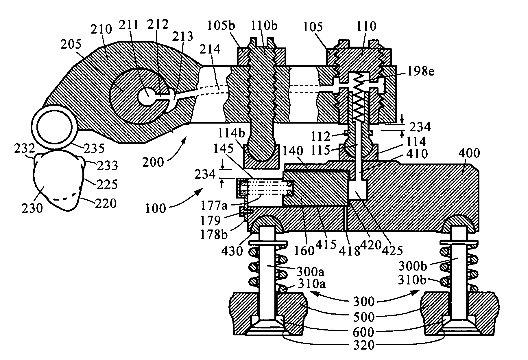
First, after the braking valve is lifted by the brake piston, the valve bridge is tilted and the followed normal valve actuation on both the braking valve and non-braking valve by the rocker arm is asymmetric or unbalanced.
Second, the brake system can only fit on a particular type of engines that have the “parallel” arrangement of the rocker arm and the valve bridge.
However, resetting the braking valve lift around the compression TDC is very problematic.
First, the duration and magnitude of the valve lift for engine braking is very small and even smaller for resetting.
Second, the resetting happens at around the peak engine braking load and causes high pressure or large load on the reset valve.
If the resetting happens too soon, there will be too much braking valve lift loss (lower lift and earlier closing) and lower braking performance.
If the resetting happens too late, the braking valve will not be able to close before the main valve event starts and cause asymmetric loading.
Therefore, the integrated rocker engine brake according to the '730 patent may not work well at high engine speeds when the reset duration and height is extremely small and the braking load or pressure on the reset valve is very high.
(a) The system can only be installed on a particular type of engines.
(b) The system has slow response (on & off) time.
(c) The system is hydraulically driven and has large compliance resulting in high braking load.
(d) The system causes asymmetric loading on valves or valve bridge guide.
(e) The system has too many parts, high complexity, and not work well at high engine speeds.
(f) The system has no easy way to set lash for engine braking valves.
(g) The system is not reliable and sensitive to external disturbances.

Method used


Image

  • Integrated engine brake with mechanical linkage
  • Integrated engine brake with mechanical linkage
  • Integrated engine brake with mechanical linkage

Examples


Embodiment Construction

[0075]Reference will now be made in detail to presently preferred embodiments of the invention, examples of which are illustrated in the accompanying drawings. Each example is provided by way of explanation, not limitation, of the invention. In fact, it will be apparent to those skilled in the art that modifications and variations can be made in the present invention without departing from the scope and spirit thereof. For instance, features illustrated or described as part of one embodiment may be used on another embodiment to yield a still further embodiment. Thus, it is intended that the present invention covers such modifications and variations as come within the scope of the appended claims and their equivalents.

[0076]FIG. 1 is a function chart illustrating the general relationship between the normal engine operation 20 and the added engine braking operation 10 according to one version of the present invention. For the normal engine operation 20, the small cam lobe(s) on the ex...


PUM


Abstract

Apparatus and method are disclosed for converting an internal combustion engine from a normal engine operation (20) to an engine braking operation (10). The engine includes exhaust valve train components comprising at least one exhaust valve (300) and at least one cam (230) for cyclically opening and closing the at least one exhaust valve (300). The apparatus comprises actuation means (100) having at least one component integrated into at least one of the exhaust valve train components, such as a rocker arm (210) or a valve bridge (400). The actuation means (100) has an inoperative position and an operative position. In the inoperative position, the actuation means (100) is retracted and the small braking cam lobes (232&233) are skipped to generate a main valve lift profile (220m) for the normal engine operation (20). In the operative position, the actuation means (100) is extended to form a mechanical linkage so that the motion from all the cam lobes (220, 232&233) is transmitted to the at least one exhaust valve (300) for the engine braking operation (10). The apparatus further comprises control means (50) for moving the actuation means (100) between the inoperative position and the operative position to achieve the conversion between the normal engine operation (20) and the engine braking operation (10). The apparatus also includes valve lash adjusting mechanism, oil retraining means (350), and engine brake reset means (150).

Description

BACKGROUND OF THE INVENTION[0001]1. Field of Invention[0002]The present invention relates generally to the braking of an internal combustion engine, specifically to engine braking apparatus integrated in the engine exhaust valve train.[0003]2. Prior Art[0004]It is well known in the art to employ an internal combustion engine as brake means by, in effect, converting the engine temporarily into a compressor. It is also well known that such conversion may be carried out by cutting off the fuel and opening the exhaust valve(s) at or near the end of the compression stroke of the engine piston. By allowing compressed gas (typically, air) to be released, energy absorbed by the engine to compress the gas during the compression stroke is not returned to the engine piston during the subsequent expansion or “power” stroke, but dissipated through the exhaust and radiator systems of the engine. The net result is an effective braking of the engine.[0005]An engine brake is desirable for an interna...

Claims


Application Information

Patent Timeline
Patent Type & Authority Patents(United States)
IPC IPC(8): F02D13/04F01L1/34
CPCF01L1/08F01L1/181F01L1/26F01L13/065F02D13/04F01L1/146F01L1/20F01L1/267F01L2105/00F01L2820/033F02D13/0246F01L2305/00
Inventor YANG, ZHOU
Owner SHANGHAI UNIVERSOON AUTOPARTS CO LTD
Why Eureka
Try Eureka