Multi-channel audio encoding and decoding

Active Publication Date: 2011-11-29
MICROSOFT TECH LICENSING LLC
View PDF161 Cites 28 Cited by
  • Summary
  • Abstract
  • Description
  • Claims
  • Application Information

AI Technical Summary

Benefits of technology

[0065]In summary, the detailed description is directed to strategies for encoding and decoding multi-channel audio. For example, an audio encoder uses one or more techniques to improve the quality and/or bitrate of multi-channel audio data. This improves the overall listening expe

Problems solved by technology

As Table 1 shows, the cost of high quality audio information is high bitrate.
High quality audio information consumes large amounts of computer storage and transmission capacity.
Many computers and computer networks lack the resources to process raw digital audio.
Compression can be lossless (in which quality does not suffer) or lossy (in which quality suffers but bitrate reduction from subsequent lossless compression is more dramatic).
The quantization and other lossy compression techniques introduce potentially audible noise into an audio signal.
Disadvantages of Standard Perceptual Audio Encoders and Decoders
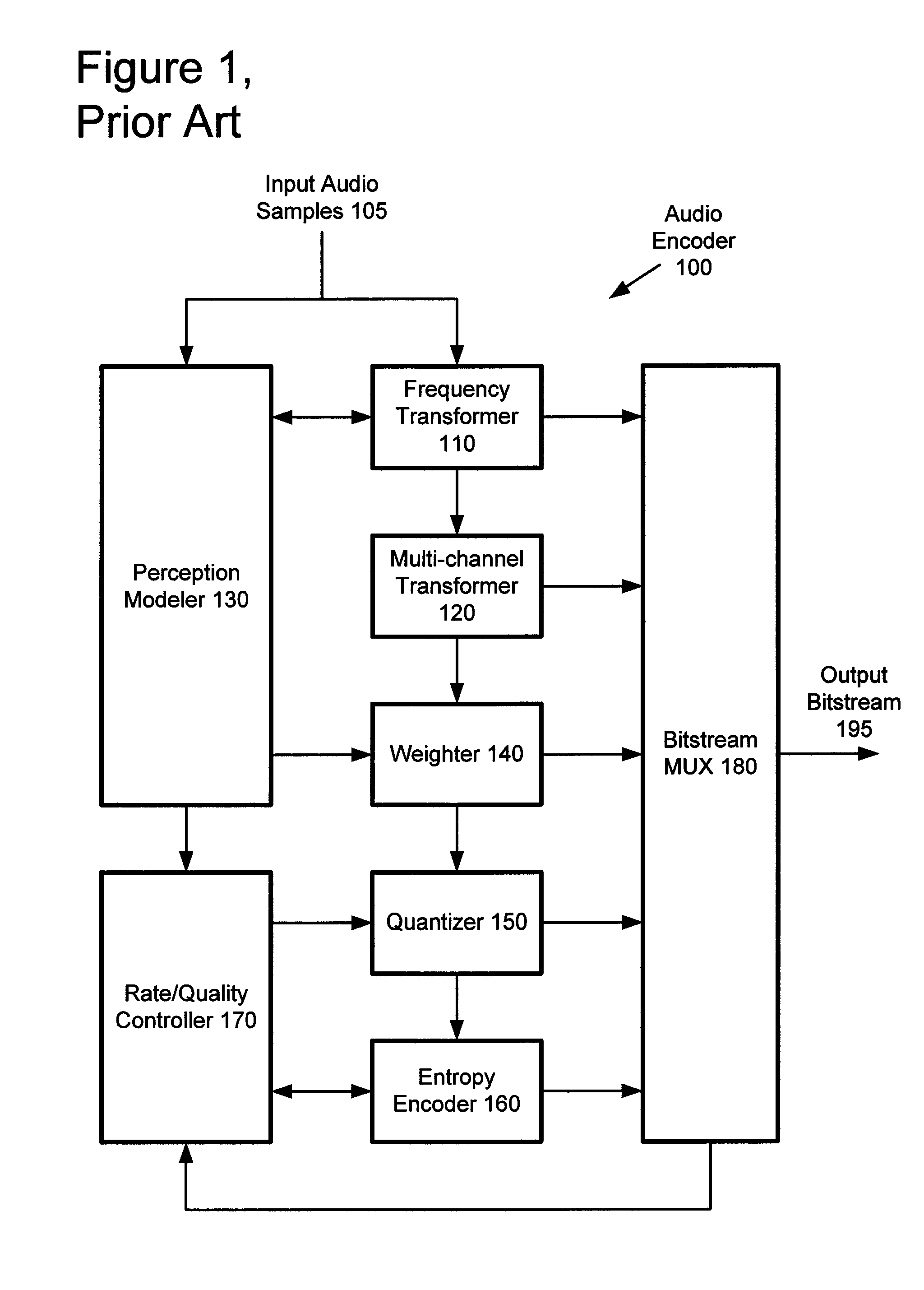
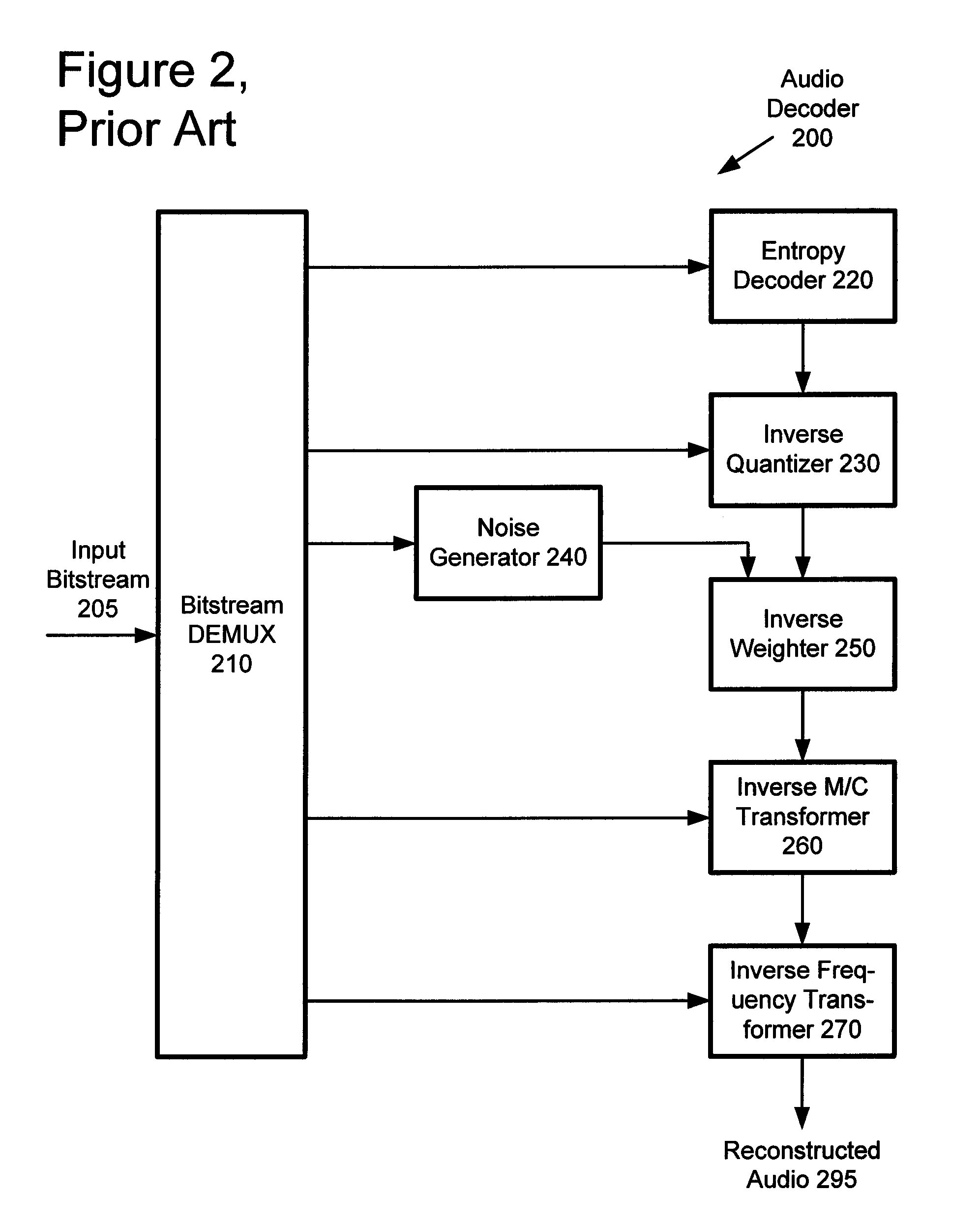
Although perceptual encoders and decoders as described above have good overall performance for many applications, they have several drawbacks, especially for compression and decompression of multi-channel audio.
The drawbacks limit the quality of reconstructed multi-channel audio in some cases, for example, when the available bitrate is small relative to the number of input audio channels.
A drawback of forcing all channels to have an identical window configuration is that a stationary signal in one or more channels (e.g., channel 1 in FIGS. 3a-3c) may be broken into smaller windows, lowering coding gains.
This problem is exacerbated when more than two channels are to be coded.
This limits the flexibility of partitioning for multi-channel transforms in the AAC system, as does the use of only pair-wise groupings.
These limitations constrain multi-channel coding of more than two channels.
Both systems give some good results, but still have several limitations.
First, using a KLT on audio samples (whether across the time domain or frequency domain as in the Yang sy

Method used


Image

  • Multi-channel audio encoding and decoding
  • Multi-channel audio encoding and decoding
  • Multi-channel audio encoding and decoding

Examples


Embodiment Construction

n a multi-channel transform in one implementation.

[0095]FIG. 19 is a flowchart showing a technique for retrieving band on / off information for a multi-channel transform for a channel group of a tile from a bitstream according to a particular bitstream syntax.

[0096]FIG. 20 is a flowchart showing a generalized technique for emulating a multi-channel transform using a hierarchy of simpler multi-channel transforms.

[0097]FIG. 21 is a chart showing an example hierarchy of multi-channel transforms.

[0098]FIG. 22 is a flowchart showing a technique for retrieving information for a hierarchy of multi-channel transforms for channel groups from a bitstream according to a particular bitstream syntax.

[0099]FIG. 23 is a flowchart showing a generalized technique for selecting a multi-channel transform type from among plural available types.

[0100]FIG. 24 is a flowchart showing a generalized technique for retrieving a multi-channel transform type from among plural available types and performing an inve...


PUM


Abstract

An audio encoder and decoder use architectures and techniques that improve the efficiency of multi-channel audio coding and decoding. The described strategies include various techniques and tools, which can be used in combination or independently. For example, an audio encoder performs a pre-processing multi-channel transform on multi-channel audio data, varying the transform so as to control quality. The encoder groups multiple windows from different channels into one or more tiles and outputs tile configuration information, which allows the encoder to isolate transients that appear in a particular channel with small windows, but use large windows in other channels. Using a variety of techniques, the encoder performs flexible multi-channel transforms that effectively take advantage of inter-channel correlation. An audio decoder performs corresponding processing and decoding. In addition, the decoder performs a post-processing multi-channel transform for any of multiple different purposes.

Description

RELATED APPLICATION INFORMATION[0001]This application is a divisional of U.S. patent application Ser. No. 12 / 121,629, filed May 15, 2008, entitled “MULTI-CHANNEL AUDIO ENCODING AND DECODING WITH DIFFERENT WINDOW CONFIGURATIONS,” which is a divisional of U.S. patent application Ser. No. 10 / 642,550, filed Aug. 15, 2003, entitled “MULTI-CHANNEL AUDIO ENCODING AND DECODING,” now U.S. Pat. No. 7,502,743, which claims the benefit of U.S. Provisional Patent Application Ser. No. 60 / 408,517, filed Sep. 4, 2002, the disclosures of which are incorporated herein by reference. The following U.S. provisional patent applications relate to the present application: 1) U.S. Provisional Patent Application Ser. No. 60 / 408,432, entitled, “Unified Lossy and Lossless Audio Compression,” filed Sep. 4, 2002, the disclosure of which is hereby incorporated by reference; and 2) U.S. Provisional Patent Application Ser. No. 60 / 408,538, entitled, “Entropy Coding by Adapting Coding Between Level and Run Length / Lev...

Claims


Application Information

Patent Timeline
IPC IPC(8): G10L19/00G10L21/00G11B20/10G10L19/02
CPCG10L19/008G10L19/0212G10L19/00
Inventor THUMPUDI, NAVEENCHEN, WEI-GE
Owner MICROSOFT TECH LICENSING LLC
Why Eureka
Try Eureka