Injector for injecting fuel into combustion chambers of internal combustion engines

a technology of injector and combustion chamber, which is applied in the direction of fuel injector, machine/engine, liquid fuel feeder, etc., can solve the problems of high leakage loss, achieve low leakage loss, reduce production cost, and tight tolerance

a technology of injector and combustion chamber, which is applied in the direction of fuel injector, machine/engine, liquid fuel feeder, etc., can solve the problems of high leakage loss, achieve low leakage loss, reduce production cost, and tight tolerance

US8069840B2Active Publication Date: 2011-12-06ROBERT BOSCH GMBH

Image

  • Injector for injecting fuel into combustion chambers of internal combustion engines
  • Injector for injecting fuel into combustion chambers of internal combustion engines
  • Injector for injecting fuel into combustion chambers of internal combustion engines

Examples


Embodiment Construction

[0018]Components that are the same and those that serve the same functions have been labeled with the same reference numerals in the drawings.

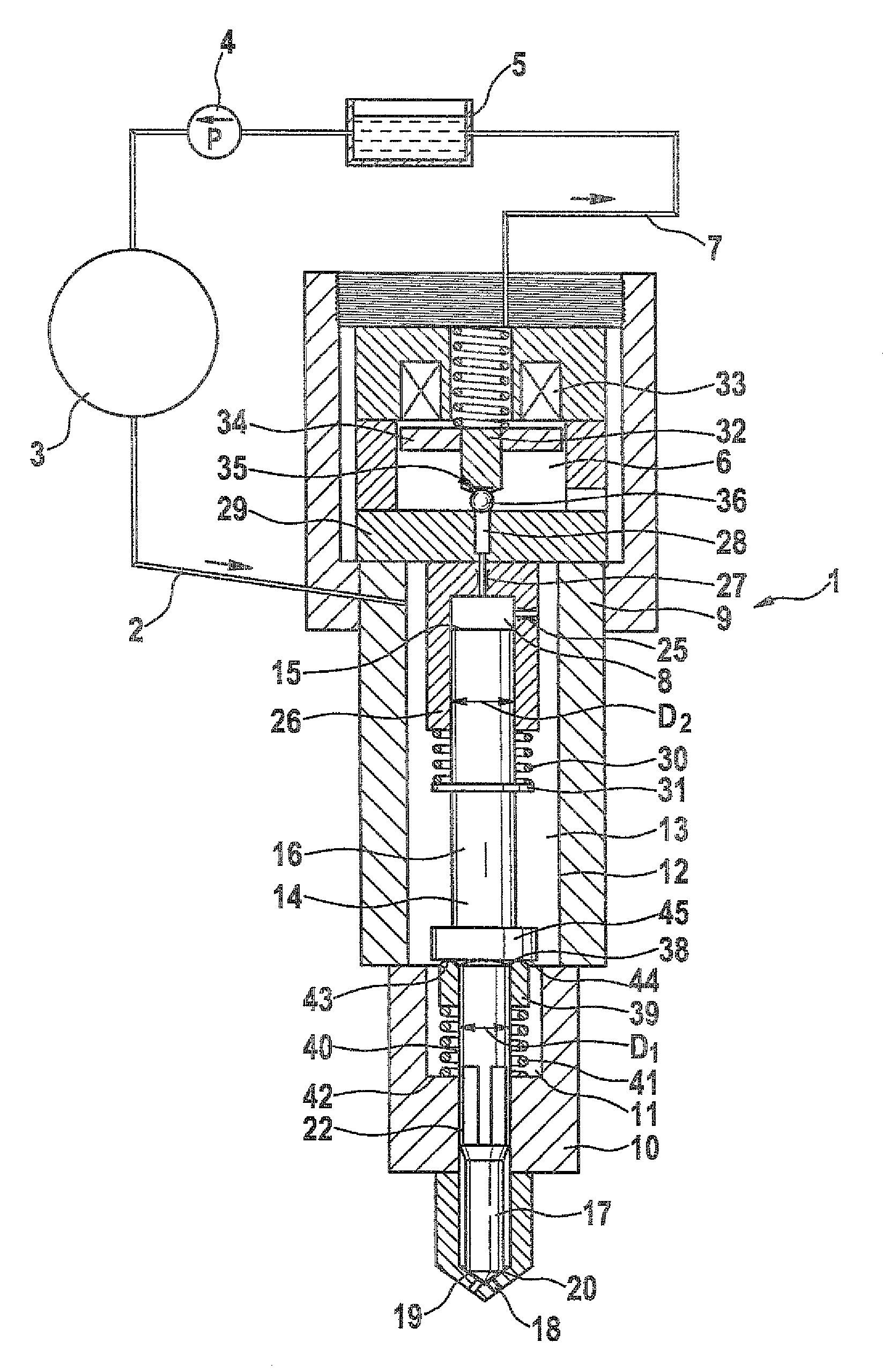
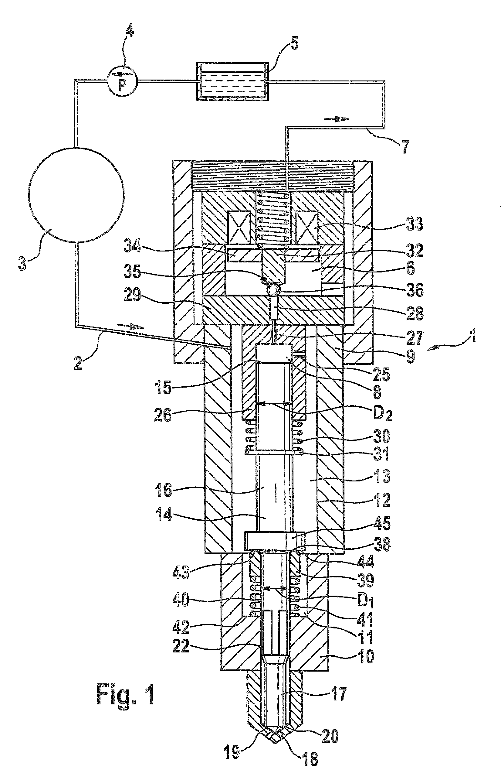
[0019]FIG. 1 shows a common rail injector 1 for injecting fuel into combustion chambers of internal combustion engines. The injector 1 is supplied with fuel, in particular diesel or gasoline, at high pressure (approx. 1800 to 2000 bar) from a high-pressure fuel reservoir 3 (rail) via a high-pressure supply line 2. A high-pressure pump 4 embodied in the form of a radial piston pump supplies the high-pressure fuel reservoir 3 with fuel from a storage tank 5 that is at low pressure. A low-pressure region 6 of the injector is hydraulically connected to the storage tank 5 via a return line 7. Depending on the operating state, the pressure in the low-pressure region of the injector lies between approximately 0 and 10 bar. The return line 7 conveys a control quantity of fuel away from a control chamber 8 and supplies it to the high-pressure circuit v...


PUM


Abstract

The invention relates to an injector for injecting fuel into combustion chambers of internal combustion engines, in particular a common rail injector. The injector has a high-pressure region and a valve element which is axially adjustable between a closed position and an open position in which the flow of fuel is enabled. According to the invention, it is provided that the valve element includes a first partial element and at least one separate second partial element, which partial elements are hydraulically coupled to one another by a coupler chamber. The coupler chamber is hydraulically connected only in one axial direction to the high-pressure region of the injector.

Description

CROSS-REFERENCE TO RELATED APPLICATION[0001]This application is a 35 USC 371 application of PCT / EP 2007 / 063393 filed on Dec. 6, 2007.FIELD OF THE INVENTION[0002]The invention relates to an injector, in particular a common rail injector.DESCRIPTION OF THE PRIOR ART[0003]DE 100 24 703 A1 has disclosed a common rail injector that is able to inject fuel directly into a combustion chamber of an internal combustion engine with which it is associated. To this end, a one-piece valve element is situated in a housing and has a pressure surface that acts on the whole in the opening direction of the valve element. At the opposite end of the valve element, a control surface is provided, which acts in the closing direction and delimits a control chamber. The control surface acting in the closing direction is on the whole larger than the pressure surface acting in the opening direction when the valve element is open. In the known injector it is disadvantageous that the one-piece embodiment of the ...

Claims


Application Information

Patent Timeline
06 Dec 2011
Publication
US8069840B2
IPC
F02M69/04
CPC
F02M47/027; F02M61/10; F02M61/12; F02M61/167; F02M2547/003; F02M2200/304; F02M2200/703; F02M2547/001
Inventors
MAGEL, HANS-CHRISTOPH