Inflatable solar concentrator balloon method and apparatus

a concentrator and balloon technology, applied in the direction of collapsible antenna means, lighting and heating apparatus, transportation and packaging, etc., can solve the problems of affecting the use of land below the modules and potentially increasing the environmental impact of solar installation, so as to facilitate feedthroughs, reduce stress concentration, and modify the inflated shape

Active Publication Date: 2011-12-13
COOLEARTH SOLAR
View PDF21 Cites 14 Cited by
  • Summary
  • Abstract
  • Description
  • Claims
  • Application Information

AI Technical Summary

Benefits of technology

[0010]Embodiments of solar energy concentration approaches according to the present invention may employ minimum-material shapes and architectures so that concentrators do not require excessive material. Moreover, embodiments of the system architecture may provide for elastic flexure under severe loads, rather than plastic bending or buckling. The conventional approach to mounting solar modules is to use an extended truss made of beams and extrusions that support compressive loads and consequently require a significant amount of material to resist bucking and distortion under wind loading, or completely separate mounts, each individually tied to a solid surface, e.g., ground via concrete pads. Such conventional mounts may offer disadvantages in that they:
[0011]may require excessive material to support tensile loads and prevent deflection;
[0013]may require excessive preparation of or access to the terrain below the modules, impacting the use of land below the modules and potentially increasing the environmental impact of solar installationsEmbodiments of the present invention accordingly employ a plurality of solid, high-aspect-ratio tensile members, herein called cables that may comprise wires, extrusions, wire rope, natural or synthetic rope, weaves, fiber-reinforced composites, fiber-reinforced ropes, cable assemblies, and the like. As used herein, the term “fastened” means at least partly constrained from relative translation in at least one direction or partly constrained from relative rotation in at least one direction over at least a finite range of motion. The mechanism that tensions the ends of the cables should be able to support the cable tension along with any lateral forces or increased tensile forces produced by the wind. One embodiment of such a mechanism is a truss which uses the cables as tensile elements and a minimum number of compressive elements to perform its function, since that arrangement should provide for minimizing the number of cable attachments and the truss material, and therefore minimizing cost.
[0014]The amount of material in a design is substantially dictated by stability specifications in the normal operating regime. To offset labor costs, embodiments according to the present invention employ novel designs to simplify and speed maintenance.
[0015]The minimum-material structure according to embodiments of the present invention, employs inflation air as a primary structural element of a concentrator, allowing the use of concentrator materials that are far thinner than any conventional concentrator.

Problems solved by technology

Such conventional mounts may offer disadvantages in that they:may require excessive material to support tensile loads and prevent deflection;may require redundant mounting and pointing apparatus; and / or;may require excessive preparation of or access to the terrain below the modules, impacting the use of land below the modules and potentially increasing the environmental impact of solar installations

Method used


Image

  • Inflatable solar concentrator balloon method and apparatus
  • Inflatable solar concentrator balloon method and apparatus
  • Inflatable solar concentrator balloon method and apparatus

Examples


embodiment 1

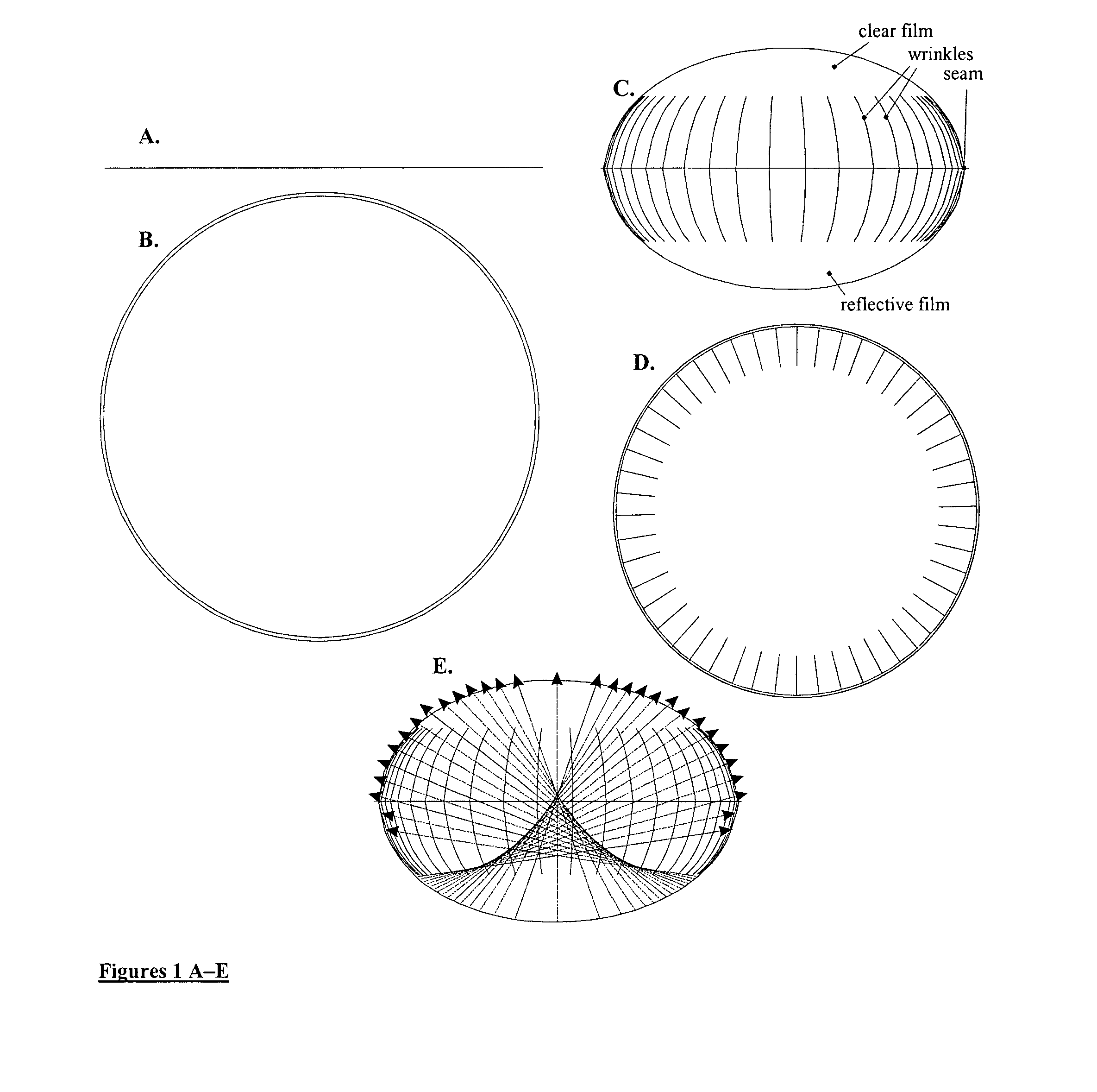
[0121]FIGS. 1A-B show views of an embodiment of an inflatable solar energy concentrator in accordance with the present invention. FIGS. 1A and 1B respectively show elevation and plan views of the substantially flat, uninflated films. The relative flatness and thinness of the uninflated films facilitates manufacturing and distribution. FIGS. 1C and 1D respectively show elevation and plan views of the inflated films. These views are based on actual measurements and accurately depict the film shape and extent of wrinkling. FIG. 1E shows where rays propagating downward parallel to the axis of the balloon (not shown) reflect after hitting the reflective film. The rays concentrate along the balloon axis, with a peak concentration near the center of the balloon. The rays diverge quickly on leaving the balloon and thus pose no external fire hazard.

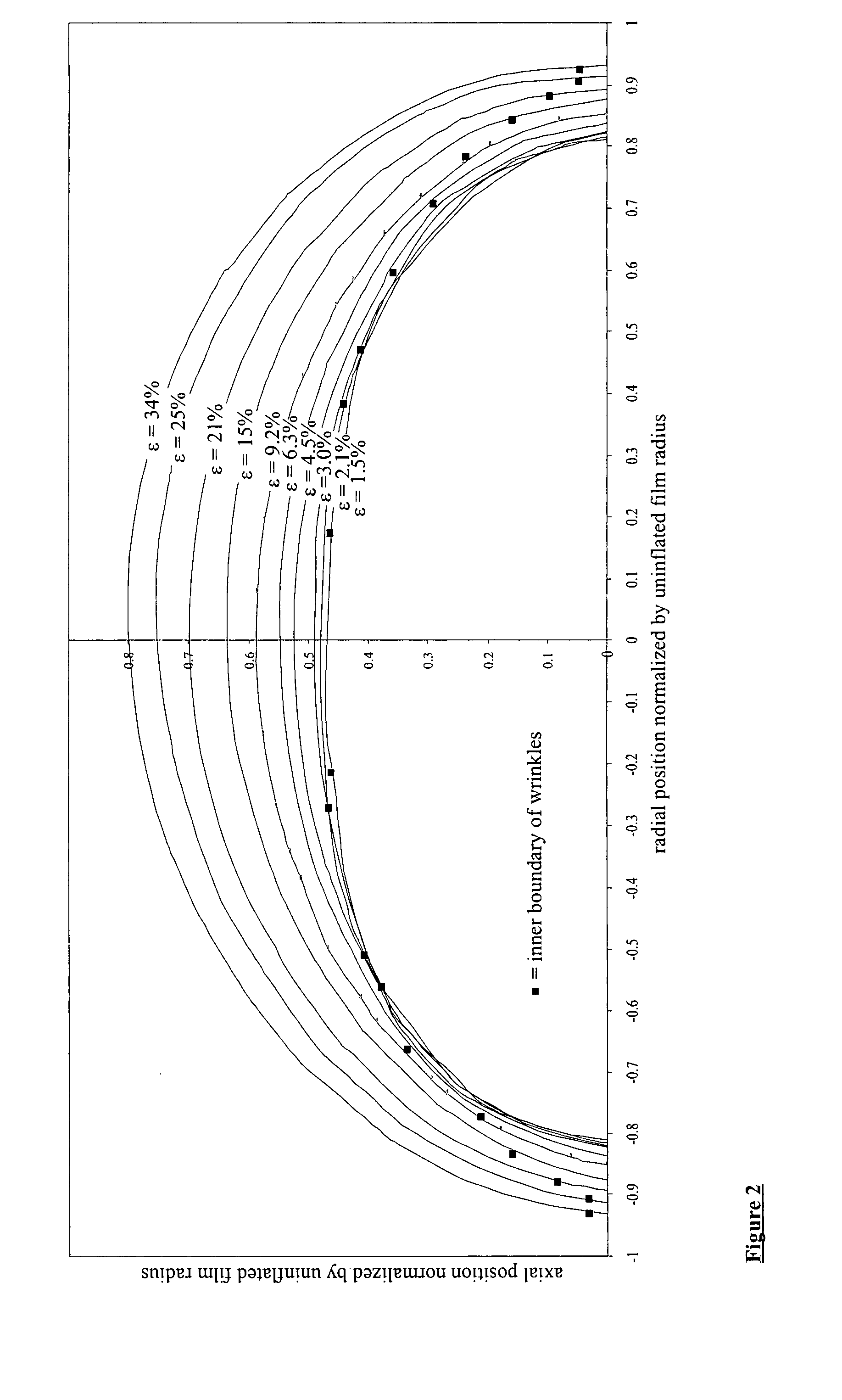
[0122]The profile and boundary of the wrinkle zone depends on the balloon strain. FIG. 2 shows measured profiles of the balloon cross-section for...


PUM


Abstract

Embodiments of the present invention relate to concentrating solar radiation using an assembly of at least one clear and one reflective film that inflates into a shape reflecting parallel rays of light to a concentrated focus in the interior or immediate proximity of the assembly. Embodiments of the present invention can be assembled in a substantially flat stack with bonds or welds between the films, compatible with conventional high-throughput film manufacturing processes. Embodiments in accordance with the present invention may employ external circumferential rings or a “harness” assembly to support and point the balloon against wind forces and the like without severe stress localization. Embodiments in accordance with the present invention may also employ film attachments to facilitate feedthroughs, reduce stress concentrations, and modify the inflated shape. Embodiments in accordance with the present invention may also employ film modifiers, including laminated films, adhesives, printing, etc. to facilitate installation, feedthroughs, and other functions.

Description

CROSS-REFERENCES TO RELATED APPLICATIONS[0001]The instant nonprovisional patent application claims priority to U.S. Provisional Patent Application No. 60 / 839,841, filed Aug. 23, 2006 and incorporated by reference in its entirety herein for all purposes. The instant nonprovisional patent application is also related to the following U.S. Provisional Patent Applications, each of which is incorporated by reference in its entirety herein for all purposes: Appl. No. 60 / 839,855, filed Aug. 23, 2006; Appl. No. 60 / 840,156 filed Aug. 25, 2006; and Appl. No. 60 / 840,110, filed Aug. 25, 2006.BACKGROUND OF THE INVENTION[0002]Solar radiation is the most abundant energy source on earth. However, attempts to harness solar power on large scales have so far failed to be economically competitive with most fossil-fuel energy sources.[0003]One reason for the lack of adoption of solar energy sources on a large scale is that fossil-fuel energy sources have the advantage of economic externalities, such as l...

Claims


Application Information

Patent Timeline
Patent Type & Authority Patents(United States)
IPC IPC(8): F24J2/08F24S90/00F24S23/30
CPCF24J2/1052Y02E10/40F24S23/81
Inventor CUMMINGS, ERIC BRYANT
Owner COOLEARTH SOLAR
Why Eureka
Try Eureka