Centerless grinder with servo motor

a servo motor and centerless technology, applied in the direction of edge grinding machines, grinding machine components, manufacturing tools, etc., can solve the problems of reducing machine precision, electric servo motor exposed to metal grinding, and need for frequent maintenance, so as to reduce conversion costs

Inactive Publication Date: 2011-12-13
COZART BRIAN
View PDF7 Cites 3 Cited by
  • Summary
  • Abstract
  • Description
  • Claims
  • Application Information

AI Technical Summary

Benefits of technology

[0005]The present invention addresses the above and other needs by providing apparatus and method for converting a conventional centerless grinding machine to a centerless grinding machine having a servo motor mounted inside the top slide using an internal servo motor bracket. The servo motor bracket is bolted to the spindle head assembly housing and is cantilevered into the top slide to allow required tilt adjustment of the regulating wheel with respect to the top slide while maintaining correct alignment of the servo motor with the regulating wheel spindle. The bracket includes slots allowing a servo motor belt tension to be adjusted. The tension adjustments are conveniently made through an existing opening in the top slide. Locating the servo motor inside the top slide using the internal servo motor bracket of the present invention significantly reduces conversion costs and servo motor maintenance otherwise required by the environment the centerless grinder is operated in, for example, oils and the presence of metal grindings.
[0006]In accordance with one aspect of the invention, there is provided a modified centerless grinding machine including a base, a grinding wheel housing mounted to the base and a top slide residing on the base opposite the grinding wheel housing and slidable towards and away from the grinding wheel housing. A grinding wheel rotatably resides in the grinding wheel housing and the regulating wheel housing is pivotally attached to the top slide facing the grinding wheel housing and slidable with the top slide. A regulating wheel spindle rotatably resides in the regulating wheel housing and is pivotable with the regulating wheel housing and the regulating wheel is attached to rotate with the regulating wheel spindle. A regulating wheel pulley is attached to the regulating wheel spindle for rotating the regulating wheel spindle and the regulating wheel. An electric motor is supported entirely inside the top slide by a cantilevered motor bracket to turn the regulating wheel and a speed reducer is attached to the electric motor for reducing the speed which the electric motor turns the regulating wheel. The cantilevered motor bracket includes a cantilevered motor bracket base attached to the regulating wheel housing and pivots with the regulating wheel housing and reaches inside the top slide. The motor is attached to the cantilevered motor bracket by a sliding bracket which is slidably attached to the cantilevered motor bracket base and slidable towards and away from the regulating wheel spindle to adjust belt or chain tension. The electric motor resides entirely inside the top slide to reduce or eliminate exposure to the hash environment the centerless grinding machine operates in.

Problems solved by technology
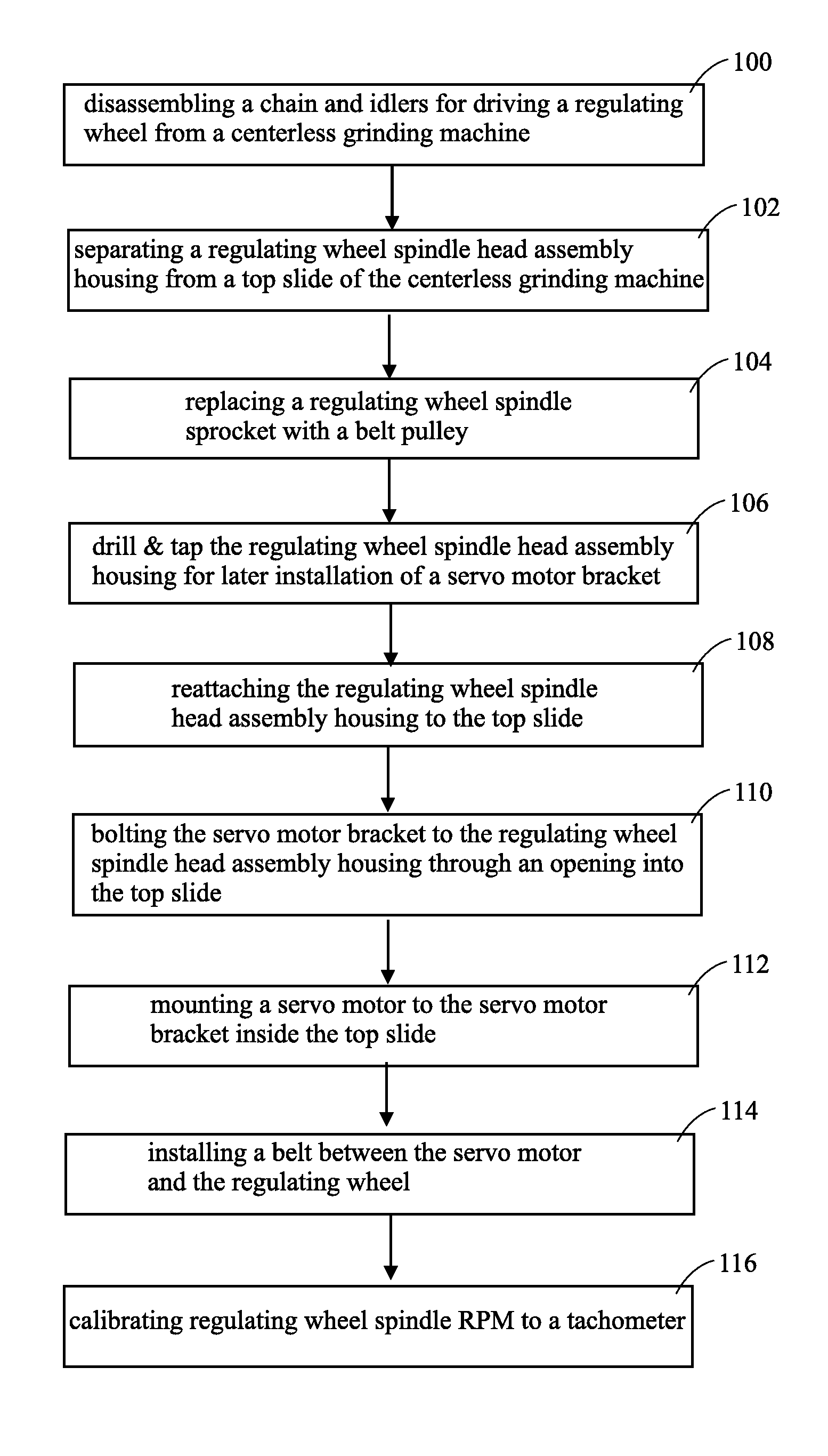
Unfortunately, the gears, chains, and idlers of convention centerless grinding machines are expensive to maintain and introduce mechanical vibrations into the regulating wheel which reduce the precision of the machine.
As a result, the electric servo motor is exposed to the metal grindings necessarily resulting from the operation of the centerless grinder.
Such exposure to very fine metal grindings creates a need for frequent maintenance and also results in shortened motor life.
Further, the regulating wheel spindle is a very expensive element of a centerless grinding machine and such replacement is very high cost.
While both the '059 and the '045 patents replace the gears, chains, and idlers with an electric servo motor, the electric servo motor is again exposed to the metal grindings resulting from the operation of the centerless grinder and results in a need for frequent maintenance and short motor life.

Method used


Image

  • Centerless grinder with servo motor
  • Centerless grinder with servo motor
  • Centerless grinder with servo motor

Examples


Embodiment Construction

[0024]The following description is of the best mode presently contemplated for carrying out the invention. This description is not to be taken in a limiting sense, but is made merely for the purpose of describing one or more preferred embodiments of the invention. The scope of the invention should be determined with reference to the claims.

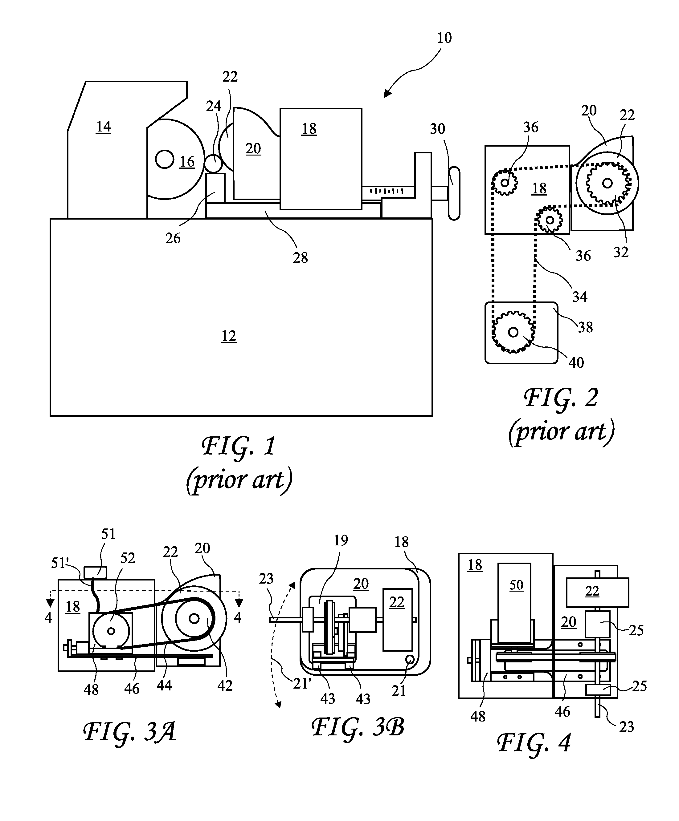
[0025]A centerless grinding machine 10 is shown in FIG. 1. The machine 10 includes a base 12, a grinding wheel housing 14, a grinding wheel 16, a top slide 18, and regulating wheel housing 20 attached to the top slide 18, a regulating wheel 22 facing the grinding wheel, and a workpiece holder 26. The workpiece holder 26 supports a cylindrical workpiece 24 which is rotated by the regulating wheel 22 and ground by the grinding wheel 16. The top slide 18 slides in rails (or ways 28) and is positionable by a top slide screw 30.

[0026]Known centerless grinding machines include a single speed electric motor, a transmission 38 having a transmission sprock...


PUM

PropertyMeasurementUnit
height HBaaaaaaaaaa
width WBaaaaaaaaaa
speedaaaaaaaaaa

Abstract

Apparatus and method for converting a convention centerless grinding machine to a centerless grinding machine having a servo motor mounted inside the top slide using an internal servo motor bracket. The servo motor bracket is bolted to the spindle head assembly housing and is cantilevered into the top slide to allow required tilt adjustment of the regulating wheel with respect to the top slide while maintaining correct alignment of the servo motor with the regulating wheel spindle. The bracket includes slots allowing a servo motor belt tension to be adjusted. The tension adjustments are conveniently made through an existing opening in the top slide. Locating the servo motor inside the top slide using the internal servo motor bracket of the present invention significantly reduces conversion costs and servo motor maintenance otherwise required by the environment the centerless grinder is operated in, for example, oils and the presence of metal grindings.

Description

BACKGROUND OF THE INVENTION[0001]The present invention relates to centerless grinding machines and in particular to conversion of a centerless grinding machine to use a servo motor to drive the regulating wheel.[0002]Centerless grinding machines have long been utilized for providing very precise cylindrical parts and very smooth finishes. The machines provide a workpiece rest for supporting a workpiece between a grinding wheel and a regulating wheel. Conventional centerless grinding machines include a large constant speed electric motor connected to the regulating wheel through a series of gears, chains, and idlers. The gears allow the speed of the regulating wheel to be selected for grinding various materials and workpiece sizes. Unfortunately, the gears, chains, and idlers of convention centerless grinding machines are expensive to maintain and introduce mechanical vibrations into the regulating wheel which reduce the precision of the machine.[0003]A known conversion for a centerl...

Claims


Application Information

Patent Timeline
Patent Type & Authority Patents(United States)
IPC IPC(8): B24B1/00
CPCB24B1/00B24B5/22B24B5/30
Inventor COZART, BRIAN
Owner COZART BRIAN
Why Eureka
Try Eureka