Microengineered optical filters that closely match predefined transmission curves and systems and methods of manufacture

a technology of transmission curves and optical filters, applied in the field of optical filters, can solve the problems of slow, expensive, difficult, if not impossible, established batch manufacturing sequences, and achieve the effect of closely matching predefined transmission spectra and micro-engineering optical filters

Inactive Publication Date: 2011-12-13
NANOPORT TECH INC
View PDF2 Cites 13 Cited by
  • Summary
  • Abstract
  • Description
  • Claims
  • Application Information

AI Technical Summary

Benefits of technology

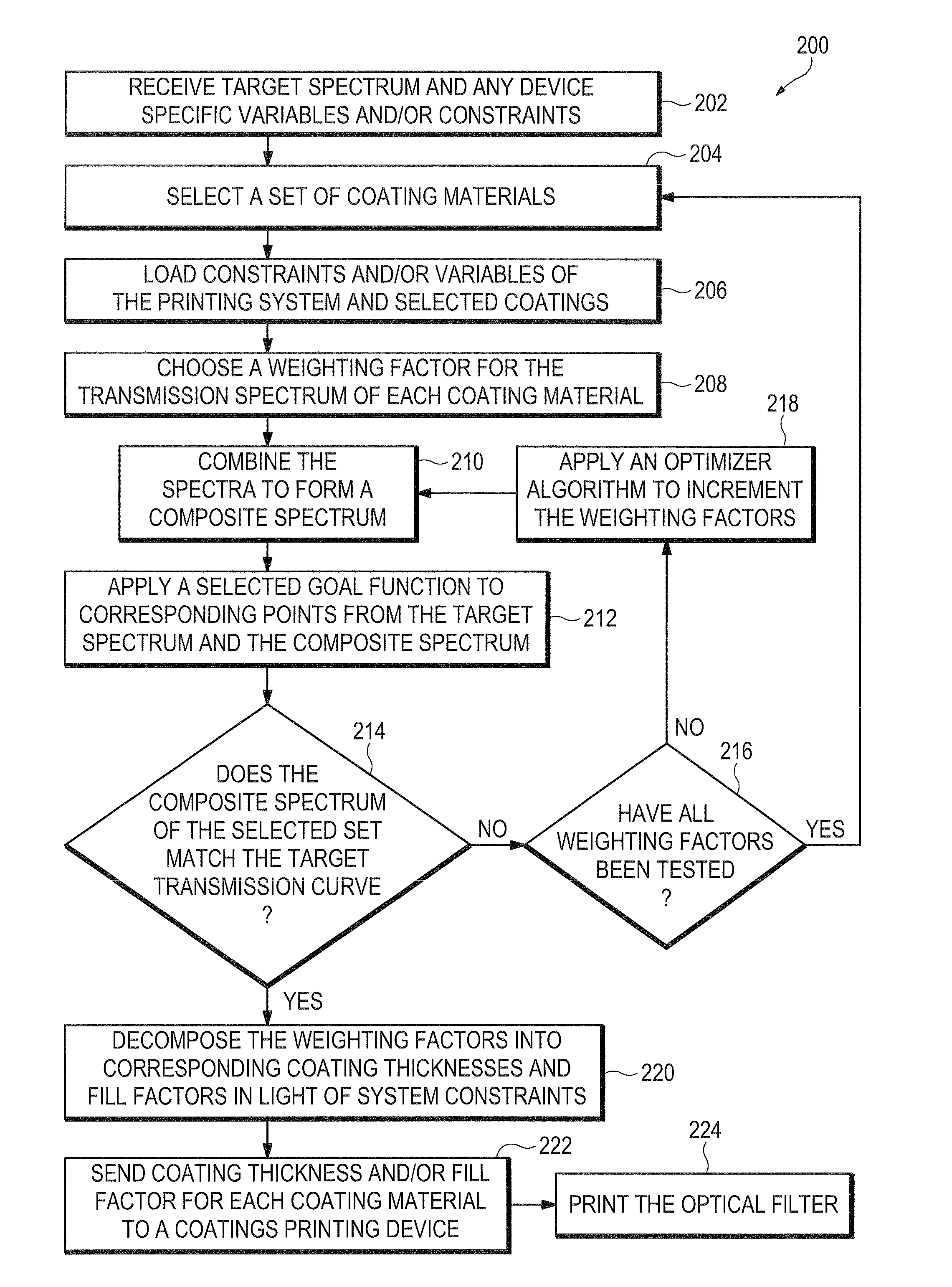
[0018]A method for creating an optical filter is herein disclosed. The method comprises sending a target transmission spectrum for an optical filter design over a network to a processor, wherein the processor is configured to select a set of one or more filter component materials based, at least in part, on a stored transmission spectrum of each component, and multiply the stored transmission spectrum of each selected filter component material by an associated component weight factor to produce a weighted transmission spectrum for each selected filter component material. The processor is further configured to combine the weighted transmission spectrum of each selected filter component material to produce a composite transmission spectrum, and optimize the value of the component weight factor associated with each component material so that the composite transmission spectrum matches the received target transmission spectrum.
[0019]A computer-readable medium having instructions stored thereon is disclosed herein. When the instructions are executed by at least one device, the instructions are configured to receive a target transmission spectrum for an optical filter design, select a set of one or more filter component materials based, at least in part, on a stored transmission spectrum of each component, and multiply the stored transmission spectrum of each selected filter component material by an associated component weight factor to produce a weighted transmission spectrum for each selected filter component material. The instructions are further configured to combine the weighted transmission spectrum of each selected filter component material to produce a composite transmission spectrum, and optimize the value of the component weight factor associated with each component material so that the composite transmission spectrum matches the received target transmission spectrum.

Problems solved by technology

All techniques utilize similar well-established batch manufacturing sequences that are slow, expensive, and only accommodate the production of optical filters whose size or “footprint” is on the order of centimeters across.
Additionally, because the control of thin film filter layer thickness is often difficult to precisely control, it can difficult, if not impossible, to manufacture thin film filters that closely match predefined transmission spectra.

Method used


Image

  • Microengineered optical filters that closely match predefined transmission curves and systems and methods of manufacture
  • Microengineered optical filters that closely match predefined transmission curves and systems and methods of manufacture
  • Microengineered optical filters that closely match predefined transmission curves and systems and methods of manufacture

Examples


Embodiment Construction

[0042]In the drawings like reference numerals generally designate identical or corresponding parts throughout the several views.

[0043]System

[0044]Referring now to FIG. 5, there is shown an exemplary computer system 50 upon which embodiments may be practiced. In general, computer system 50 comprises a processor 56 and a printing device 62. A target spectrum of an optical filter 52 is received by processor 56 through various means comprising through a network, the internet, or any type of computer readable media such as a floppy disk, a CD, a DVD, a flashdrive, a zipdrive, a hard disk, or the like. FIG. 5 shows the example where the target spectrum 52 is received from a network device, for example a remote processor, by processor 56 through a network 66, such as the internet. Such receiving means may include receipt through a webserver or through a website or webportal. The target spectrum 52 may be displayed on an imaging device 54. The imaging device 54 may include any conventional ...


PUM

PropertyMeasurementUnit
incident areaaaaaaaaaaa
diameteraaaaaaaaaa

Abstract

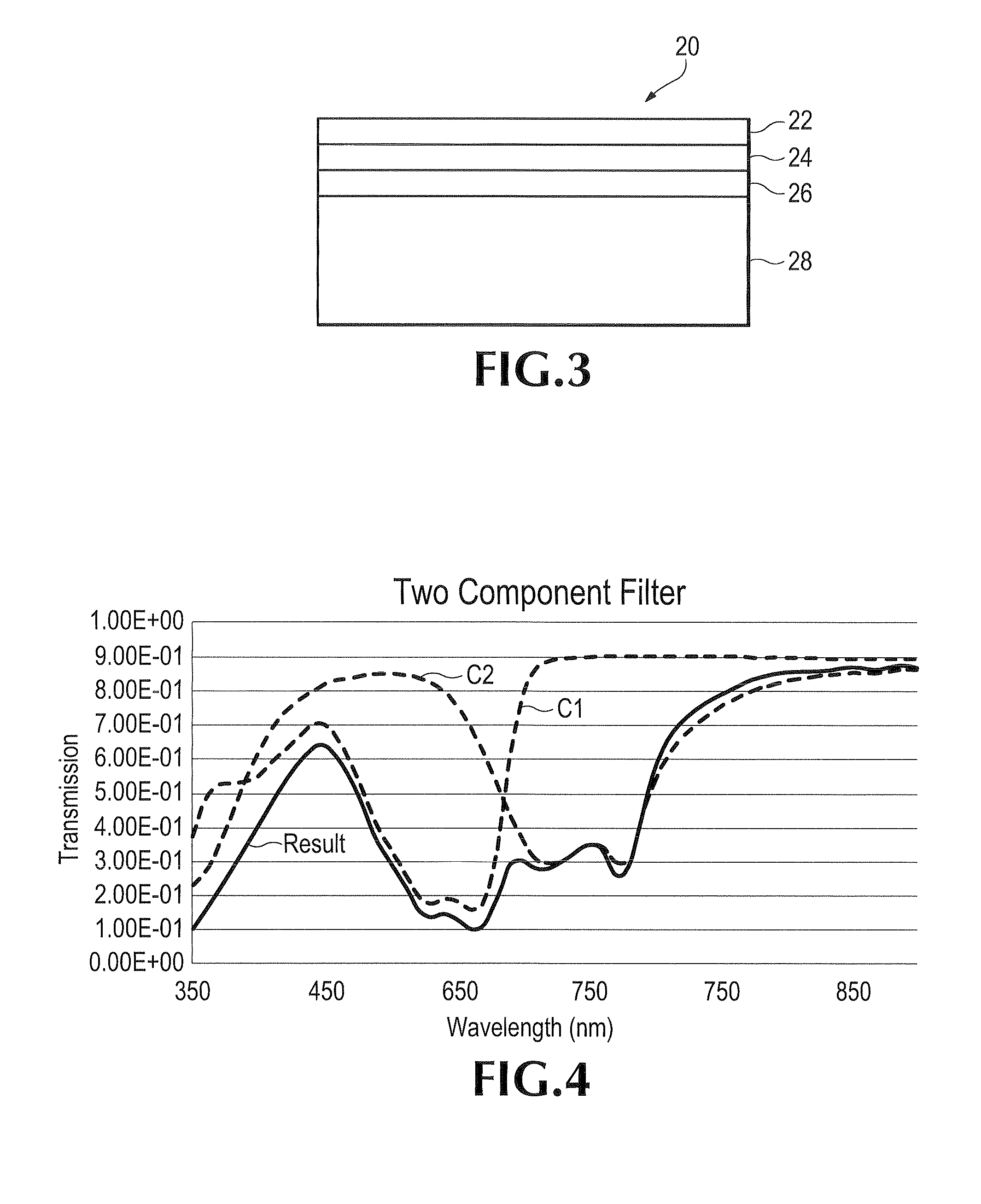
Disclosed are methods for producing optical filters on a substrate. In particular, methods for producing microengineered optical filters for the ultraviolet/visible/infrared portions of the electromagnetic spectrum are disclosed, as well as a computer-based system and method for precisely matching predefined target transmission spectra using various coating materials whose spectra can be combined and weighted for the matching. In addition, methods for producing printed optical filters comprising multiple coating components to produce composite optical filters whose transmission spectra match predefined target filter spectrum specifications are disclosed, where the thickness and fill factor of each component coating is tailored, based on the weighting of each component coating transmission spectrum.

Description

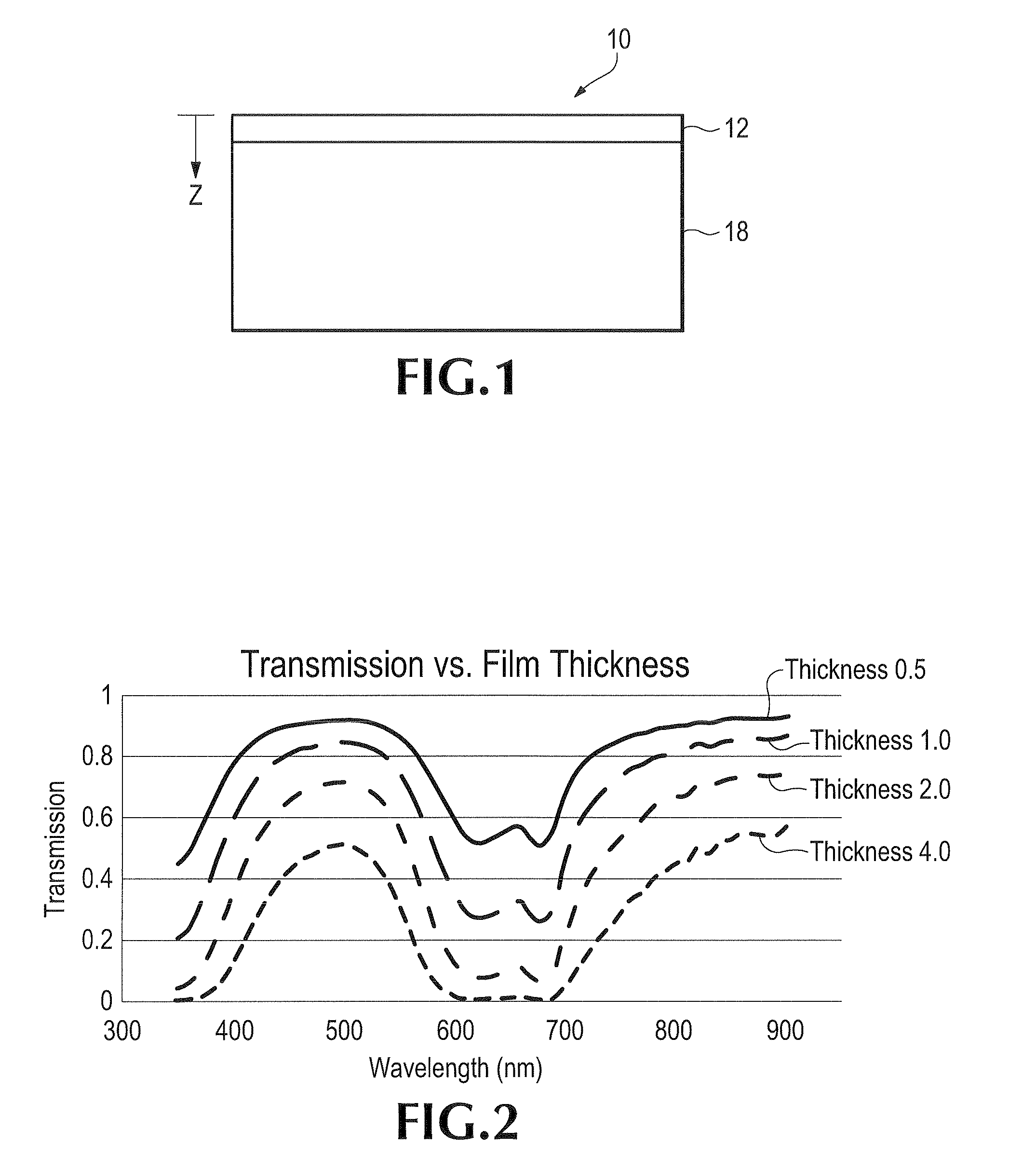
RELATED APPLICATION DATA[0001]This application claims priority from U.S. provisional application Ser. No. 61 / 038,707 filed Mar. 21, 2008, that we incorporate by reference.FIELD OF THE INVENTION[0002]The present invention relates to optical filters whose transmission spectra closely match predefined transmission spectra specifications.BACKGROUND OF THE INVENTION[0003]Optical filters, which are filters used to filter electromagnetic radiation in the ultraviolet / visible / infrared portions of the electromagnetic spectrum, are used in a multitude of applications, and typically consist of continuous thin films that are deposited on a substrate. FIG. 1 shows an optical filter 10, which comprises a thin film 12 that has been deposited on substrate 18.[0004]The intensity of light in a non-conductive media at thickness z, shown in FIG. 1, is given byI=I0e^(−αz)[0005]where I is the intensity at depth z, I0 is the intensity at a reference thickness, and α is the absorption coefficient of the mat...

Claims


Application Information

Patent Timeline
Patent Type & Authority Patents(United States)
IPC IPC(8): C23C16/52
CPCG02B5/281G02B5/283
Inventor MURAY, ANDREW JULIUSMURAY, KATHLEEN
Owner NANOPORT TECH INC
Why Eureka
Try Eureka