Optical recording medium and method for manufacturing the same

a technology of optical recording medium and manufacturing method, which is applied in the direction of photomechanical equipment, instruments, transportation and packaging, etc., can solve the problems of narrowed recording power margin, achieve good signal characteristics, promote reaction, and preserve stability high

Inactive Publication Date: 2011-12-13
SONY CORP
View PDF16 Cites 0 Cited by
  • Summary
  • Abstract
  • Description
  • Claims
  • Application Information

AI Technical Summary

Benefits of technology

[0005]In the case of using the oxide of germanium (Ge) as a recording material, since a recording principle is fundamentally based on a thermal recording, linear velocity dependency of the recording sensitivity has a certain predetermined ratio and the linear velocity dependency of the recording characteristics such as a power margin is small. Therefore, in order to raise the recording sensitivity at the time of the high linear velocity recording, it is effective to raise the recording sensitivity even at a low linear velocity. In order to assure the wide power margin at this time, a method of similarly assuring the wide power margin even at the low linear velocity becomes an index of improving the whole characteristics.
[0006]It is, therefore, an object of the invention to provide an optical recording medium which can realize a wide power margin and a method for manufacturing such a medium.
[0017]According to the invention, when recoding light is irradiated, oxygen contained in the second recording film is separated and a Ge layer whose oxygen content is large is formed at an interface between the first recording film and the second recording film. That is, the second recording film is separated into two stable layers in which optical constants are different and preservation stability is high. Thus, when reproducing light is irradiated, there is a change between a reflection light amount of a portion where the recoding light is irradiated and a reflection light amount of a portion where the recoding light is not irradiated, so that good signal characteristics are obtained. Physical characteristics of the first recording film hardly change between timing before the recording and timing after the recording but what is called a catalytic operation adapted to promote a reaction at an interface with the second recording film is caused.

Problems solved by technology

However, if the high recording sensitivity is realized by optimizing an oxygen composition and a film thickness of the first recording film containing the germanium (Ge) oxide, a film thickness of the second recording film containing titanium (Ti), and the like, such a problem that a recording power margin is narrowed occurs.

Method used


Image

  • Optical recording medium and method for manufacturing the same
  • Optical recording medium and method for manufacturing the same
  • Optical recording medium and method for manufacturing the same

Examples


first embodiment

(1) First Embodiment

Construction of Optical Recording Medium

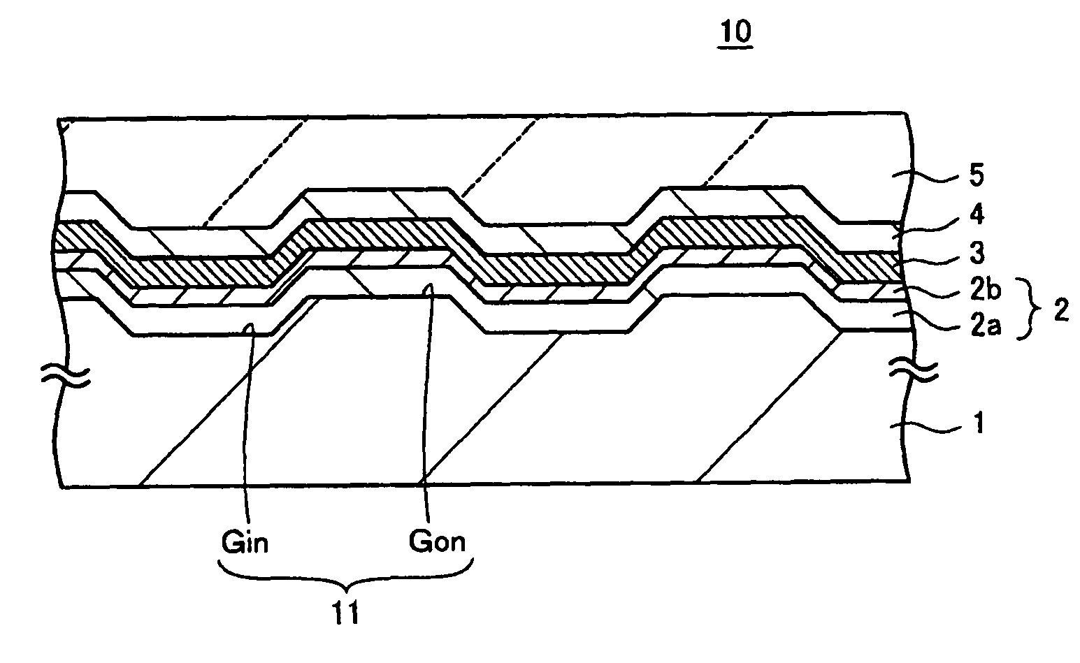
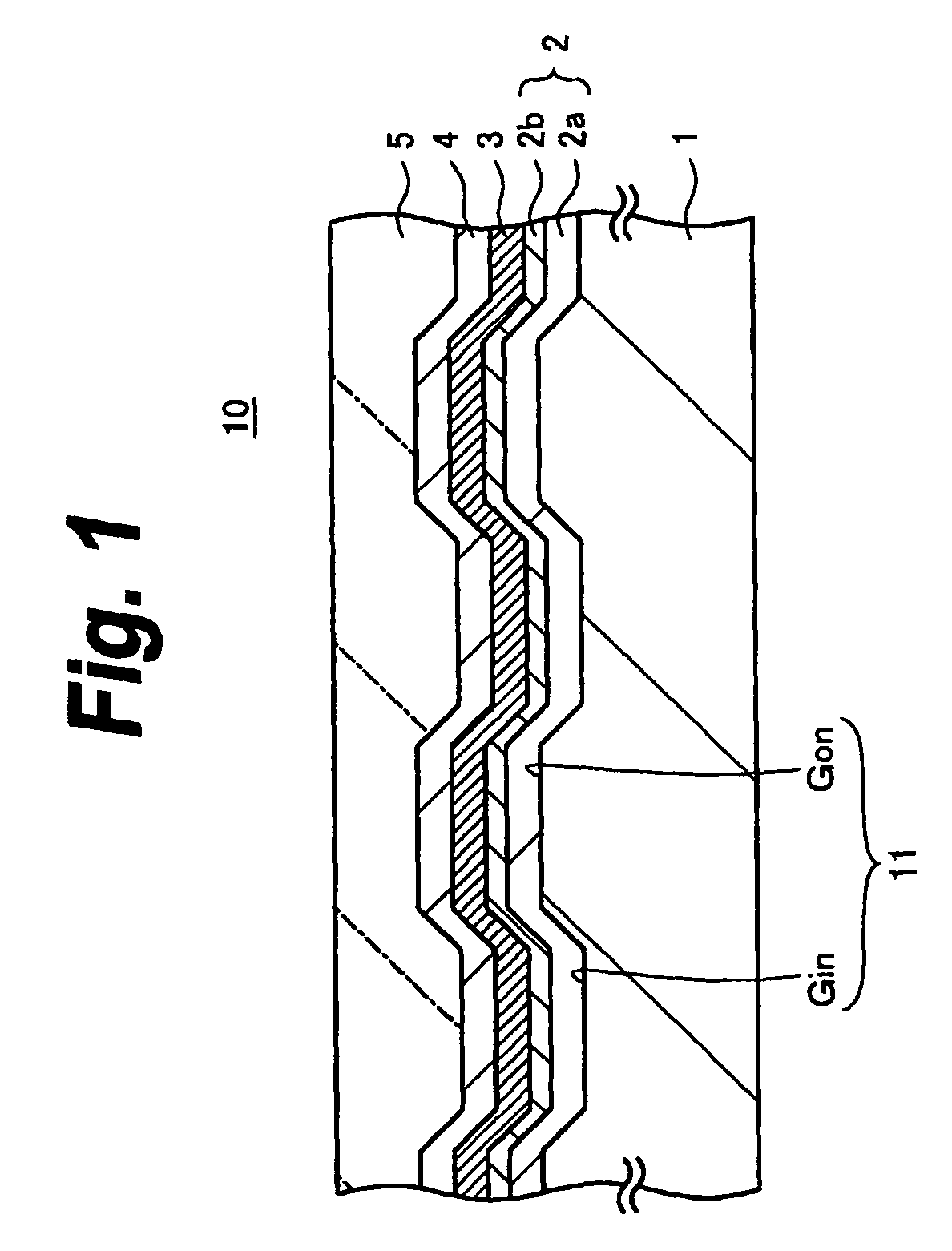
[0025]FIG. 1 is a schematic cross sectional view showing a constructional example of an optical recording medium according to the first embodiment of the invention. An optical recording medium 10 has a construction in which an inorganic recording film 2, a transparent conductive film 3, a dielectric film 4, and a light transmitting layer 5 are sequentially laminated onto a substrate 1.

[0026]In the optical recording medium 10 according to the first embodiment, by irradiating a laser beam from the side of the light transmitting layer 5 onto the inorganic recording film 2, a recording or reproduction of an information signal is performed. For example, the laser beam having a wavelength in a range from 400 nm or more to 410 nm or less is converged by an objective lens having a numerical aperture in a range from 0.84 or more to 0.86 or less and irradiated from the side of the light transmitting layer 5 to the inorganic recording...

second embodiment

(2) Second Embodiment

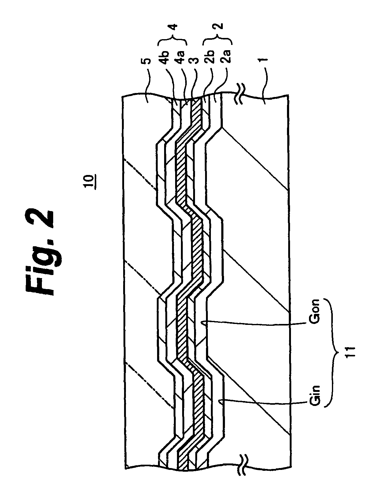
[0082]FIG. 2 is a schematic cross sectional view showing a constructional example of an optical recording medium according to the second embodiment of the invention. According to the second embodiment, the dielectric film 4 is formed by a first dielectric film 4a and a second dielectric film 4b in the foregoing first embodiment. Portions similar to those in the foregoing first embodiment are designated by the same reference numerals and their description is omitted.

[0083]The first dielectric film 4a is provided on the side of the transparent conductive film 3. The second dielectric film 4b is provided on the side of the light transmitting layer 5. The first dielectric film 4a and second dielectric film 4b are made of, for example, dielectric materials of different materials and / or compositions.

[0084]As a material of the first dielectric film 4a, it is preferable to use ZnS—SiO2 from a viewpoint of a film forming speed or the like. A film thickness of first diele...

examples 1-1 to 1-6

Comparison 1-1

[0109]In Examples 1-1 to 1-6 and Comparison 1-1, by providing the transparent conductive films 3 having different film thicknesses between the inorganic recording film 2 and the dielectric film 4, the optical recording medium 10 was manufactured and its characteristics were evaluated.

[0110]First, the polycarbonate substrate (hereinbelow, referred to as a PC substrate) 1 having a thickness of 1.1 mm was manufactured by injection molding. In addition, the concave / convex surface 11 having the in-groove Gin and the on-groove Gon was formed on the PC substrate 1. A depth of in-groove Gin was set to 20 nm and a track pitch was set to 0.32 μm.

[0111]Subsequently, the TiMnN film 2a having a thickness of 22 nm, the Ge oxide film 2b having a thickness of 25 nm, the SnO2 film 3 having a thickness of 0 to 6 nm, the ZnS—SiO2 film 4a having a thickness of 52 nm, and the Si3N4 film 4b having a thickness of 4 nm were sequentially formed on the substrate 1 by using a film forming appara...


PUM

PropertyMeasurementUnit
thicknessaaaaaaaaaa
wavelengthaaaaaaaaaa
thicknessaaaaaaaaaa

Abstract

An optical recording medium is an optical recording medium having an inorganic recording film and has a transparent conductive film on the inorganic recording film. The inorganic recording film has a first recording film containing titanium (Ti) and a second recording film containing an oxide of germanium (Ge). The transparent conductive film is provided on the side of the second recording film. The transparent conductive film contains an oxide of tin (Sn).

Description

TECHNICAL FIELD[0001]The invention relates to an optical recording medium and a method for manufacturing the same. More particularly, the invention relates to an optical recording medium having an inorganic recording film.BACKGROUND ART[0002]In recent years, an optical recording medium of a high-density recording in which information of a large volume can be recorded is demanded. For example, to meet the demand, the standard of a Blu-ray Disc (registered trademark: hereinbelow, referred to as BD) has been specified and a high-definition image can be recorded and stored into the optical recording medium. Assuming that a normal reproducing speed of the high-definition is a one-time speed, according to the BD of the recording type, the disc has already coped with the recording of up to a 2-times speed.[0003]For example, as an optical recording medium suitable for a blue laser recording, a medium having an inorganic recording film constructed by a first recording film containing an oxid...

Claims


Application Information

Patent Timeline
Patent Type & Authority Patents(United States)
IPC IPC(8): B32B3/02G11B7/24G11B7/24035G11B7/243G11B7/2433G11B7/254G11B7/257
CPCG11B7/2433G11B7/2437G11B7/266G11B2007/24304Y10T428/21G11B2007/2432G11B2007/24322G11B2007/2571G11B2007/25715G11B2007/24312G11B7/26
Inventor SAKAI, TAKEMITSUIKEDA, ETSUROSABI, YUICHI
Owner SONY CORP
Why Eureka
Try Eureka