Battery charging method and device thereof

a battery and charging method technology, applied in the direction of electrochemical generators, secondary cell servicing/maintenance, transportation and packaging, etc., can solve the problems of significantly risk, low usage efficiency, and low storage capacity, so as to save the battery and retard the deterioration

Active Publication Date: 2011-12-13
ACER INC
View PDF4 Cites 9 Cited by
  • Summary
  • Abstract
  • Description
  • Claims
  • Application Information

AI Technical Summary

Benefits of technology

[0007]Therefore, one of objectives of the present invention is to provide a battery charging method and device thereof to charge battery module safer and retard deterioration of the battery.

Problems solved by technology

A deteriorated battery not only causes lower storage capacity and low usage efficiency, but also creates a significantly risk due to the overcharging of the cell blocks, since the terminal voltage difference of normal cell blocks is normally greater than normal cell blocks during charging operation. FIGS. 1A and 1B illustrates a schematic view of voltage distribution in accordance with a battery module having a plurality of normal and deteriorated cell blocks respectively.
Hence if cell block 102 remains deteriorated, the terminal voltage of cell block 102 would increase accordingly and may result in hazardous explosion by cell block 102.
In order to ensure the battery module fully charged, the conventional charging method typically supplies the charging voltage exceeding the safety load limit of the battery module, resulting in deteriorated scenario of the cell blocks after a long term period.
Besides, though the battery module equips both over voltage protection as well as over current protection mechanisms, such mechanisms are designed for entire battery module, it is not able to reduce the risk caused by a single deteriorated cell block.

Method used


Image

  • Battery charging method and device thereof
  • Battery charging method and device thereof
  • Battery charging method and device thereof

Examples


first embodiment

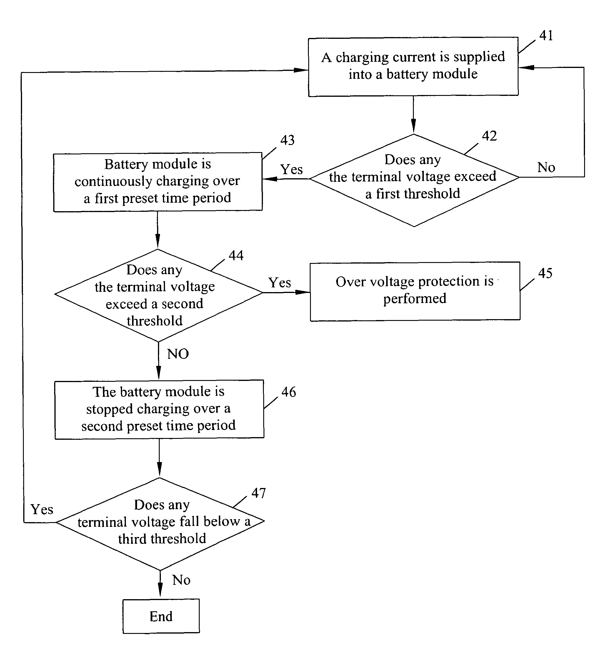
[0056]FIG. 4 illustrates a flow chart of first embodiment of the battery charging method in accordance with the present invention. The method includes the following steps. In step 41 a charging current is supplied into a battery module having a plurality of cell blocks for charging. In step 42 the terminal voltages of the cell blocks is detected for determining whether or not one of the terminal voltages exceeds a first threshold. If no terminal voltage exceeds a first threshold, then step 41 is proceeded.

[0057]If one of the terminal voltages exceeds a first threshold, the battery module is continuously charging over a first preset time period in step 43, and then the terminal voltages of cell blocks are determined whether or not one of the terminal voltages exceeds a second threshold in step 44. If one of the terminal voltages exceeds a second threshold, it indicates that one of the cell blocks is deteriorated, such that the over voltage protection is performed in step 45 to avoid ...

second embodiment

[0062]FIG. 5 illustrates a flow chart of second embodiment of the battery charging method in accordance with the present invention. The method includes the following steps. In step 51 a charging current is supplied into a battery module having a plurality of cell blocks for charging. In step 52 the terminal voltages of the cell blocks are detected for determining whether one of the terminal voltages exceeds a first threshold. If no terminal voltage exceeds the first threshold, the step 51 is proceeded.

[0063]If one of terminal voltage exceeds the first threshold, the cell blocks are continuously charged over a first preset time period in step 53, and then in step 54, terminal voltages are determined whether or not one of them exceeds a second threshold, if yes, an over voltage protection is performed in step 55, in which at least one cell blocks is determined to be deteriorated, such that the over voltage protection is performed to avoid risks.

[0064]If no terminal voltage exceeds the...

third embodiment

[0067]FIG. 6 illustrates a flowchart of third embodiment of the battery charging method in accordance with the present invention. The method includes the following steps. In step 61 a charging current is supplied into a plurality of cell blocks of a battery module for charging. In step 62 the terminal voltages of the cell blocks are determined whether or not one of terminal voltages exceeds a first threshold. If no terminal voltage exceeds a first threshold, then the step 61 is proceeded.

[0068]If one of terminal voltages exceeds the first threshold, the battery module is continuously charged over a first preset time period in step 63, and then in step 64 the terminal voltages are determined whether or not one of them exceeds a second threshold, for determining if deteriorated cell blocks exist among cell blocks. If one of terminal voltages exceeds a second threshold, it indicates that the battery module is determined having deteriorated cell blocks among normal cell blocks, so an ov...


PUM

PropertyMeasurementUnit
terminal voltageaaaaaaaaaa
terminal voltagesaaaaaaaaaa

Abstract

A battery charging method and device thereof are disclosed. The method includes the following steps. First, a charging current is supplied into a plurality of cell blocks of a battery module for charging, and the terminal voltages of the cell blocks are detected, when one of said terminal voltages exceeds a first threshold, the charging is kept continuously over a first preset time period. If one of said terminal voltages of said cell blocks exceeds a second threshold, an over voltage protection is performed, else the charging current is reduced and the battery module is charged by the reduced charging current continuously over a second preset time period and if the cell blocks are determined that they are fully charged, the charging is stopped, otherwise, the battery module is charged continuously. Therefore, the battery charging method and device thereof in accordance with the present invention can prevent the battery module from being overcharged and prolong its life.

Description

FIELD OF THE INVENTION[0001]The invention relates a battery charging method and device thereof, and more particularly to a battery charging method and device capable of retarding deterioration of the battery.BACKGROUND OF THE INVENTION[0002]As the technology grows and advances rapidly, the battery becomes an electrical power source which is not considerably replaceable and been extensively used for devices as MP3 player, cellular phone, notebook computer, electric vehicle and the likes. Therefore, a variety of charging means for battery have been proposed, such as “Constant Trickle Current Charge”, “Constant Current Charge”, “Constant Current Constant Voltage Charge” and “Two-Step Charging”, etc.[0003]Battery aging is known as a very important topic in battery technology. A deteriorated battery not only causes lower storage capacity and low usage efficiency, but also creates a significantly risk due to the overcharging of the cell blocks, since the terminal voltage difference of nor...

Claims


Application Information

Patent Timeline
Patent Type & Authority Patents(United States)
IPC IPC(8): H01M10/44H01M10/46
CPCH02J7/0022H02J7/0091Y02T10/7055Y02T10/70H02J7/0013H02J7/007182
Inventor KO, HUI PINJUAN, KUAN-CHI
Owner ACER INC
Why Eureka
Try Eureka