Energy absorbing blast wall for building structure

a technology for building structures and blast walls, applied in the direction of building roofs, ceilings, shock-proofing, etc., can solve the problems of wall assembly damage, deformation, deformation, and eventually permanent portion of deformation, so as to resist destructive movement, preserve the integrity of critical attachments, and reduce the tendency of clip straightening

Active Publication Date: 2011-12-20
SPECIALTY HARDWARE LLC
View PDF23 Cites 29 Cited by
  • Summary
  • Abstract
  • Description
  • Claims
  • Application Information

AI Technical Summary

Benefits of technology

[0005]A blast wall assembly and the components described herein form an integrated system that effectively absorbs blast energy. Unlike conventional systems, the components of the blast wall assembly function in a manner similar to highway “crumple zones” by absorbing the energy generated by the sudden impact of a blast wave on the exterior surface of the blast wall. The components of the blast wall assembly flex, move, compress, crush and bend before the full magnitude of the blast load is transmitted via the components to the fasteners used to secure the assembly to the structure. By absorbing the sudden impact of energy, the system greatly reduces the likelihood of component failure and fastener failure. Although the blast wall assembly may incur repairable damage, the blast wall assembly absorbs a substantial portion of the blast energy rather than imploding into the interior space of the structure. Thus, the blast wall assembly greatly enhances the safety of the building structure and the occupants of the building structure.
[0006]When a blast pressure wave first impacts an exterior blast board, the exterior blast board resists penetration by objects, such as rocks and shrapnel, which may be hurled against the wall by the blast force. A portion of the energy of the blast wave is absorbed by flexural bending of the exterior blast board. The load applied to the exterior blast board by the blast pressure wave is transferred to vertical wall studs. The exterior blast board also provides lateral bracing for the vertical studs, which helps prevent torsional failure of the light gauge vertical studs. The exterior blast board also serves as a substrate for a variety of exterior finish systems that may be applied to the cementitious wall board forming the outer face of the exterior blast board. Thus, from the outside, the blast wall assembly may be configured to have the cosmetic appearance of a conventional wall.
[0007]The light gauge (e.g., 16 gauge) vertical wall studs are flexible. Thus, when the load from the blast pressure wave is applied to the wall studs via the outer blast pane, the wall studs bend and deform and eventually stretch. The magnitude of deformation of the wall studs may exceed the yield strength of the wall studs and cause a portion of the deformation to be permanent. The bending, deformation and stretching of the studs absorbs additional blast energy.

Problems solved by technology

Although the blast wall assembly may incur repairable damage, the blast wall assembly absorbs a substantial portion of the blast energy rather than imploding into the interior space of the structure.
Thus, when the load from the blast pressure wave is applied to the wall studs via the outer blast pane, the wall studs bend and deform and eventually stretch.
The magnitude of deformation of the wall studs may exceed the yield strength of the wall studs and cause a portion of the deformation to be permanent.

Method used


Image

  • Energy absorbing blast wall for building structure
  • Energy absorbing blast wall for building structure
  • Energy absorbing blast wall for building structure

Examples


Embodiment Construction

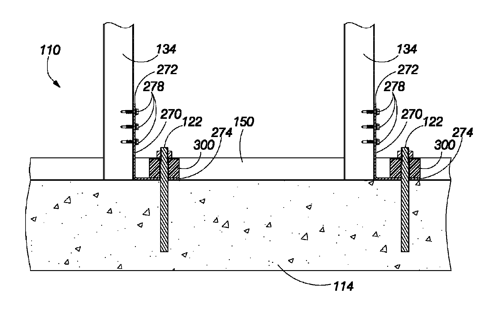
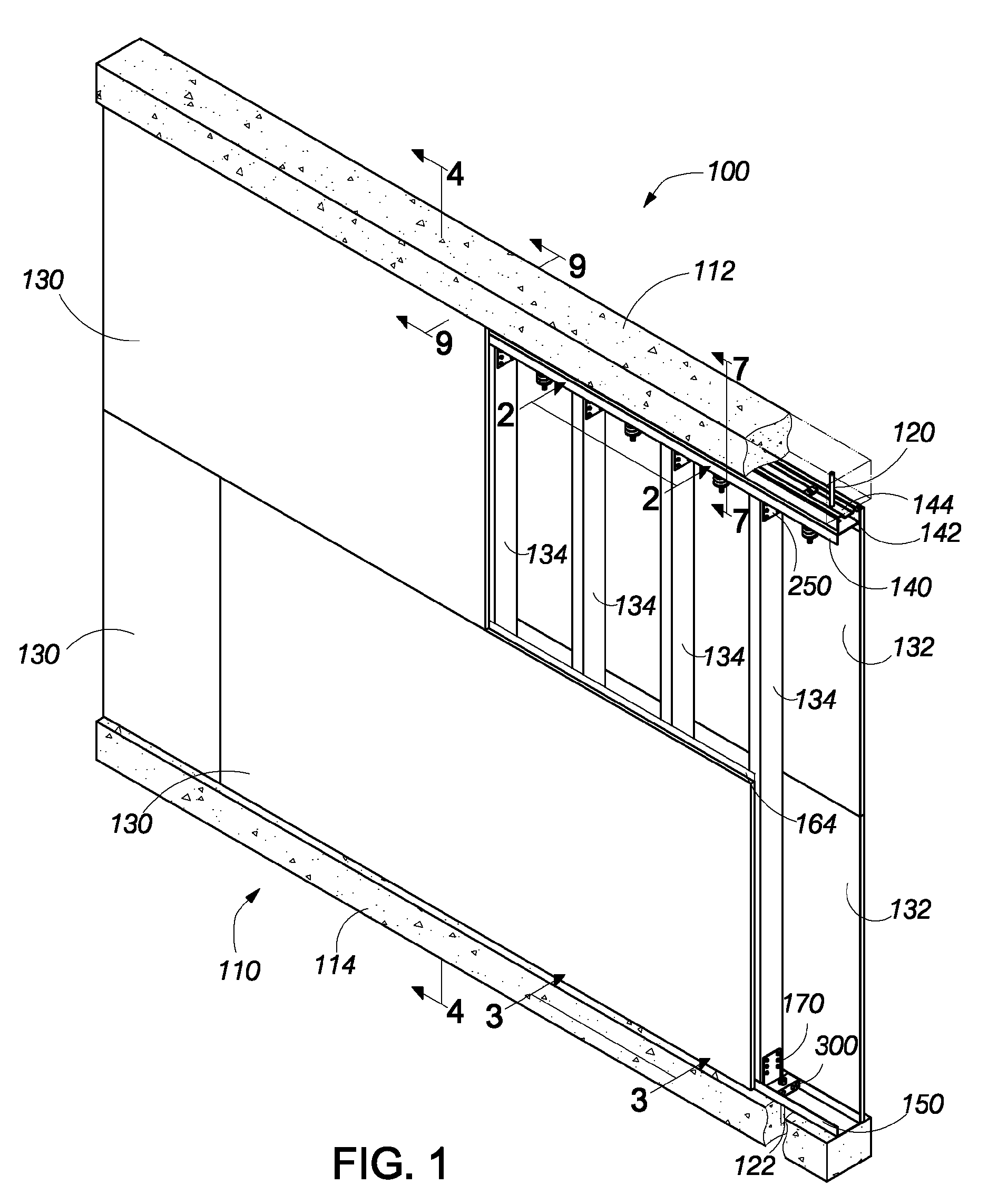
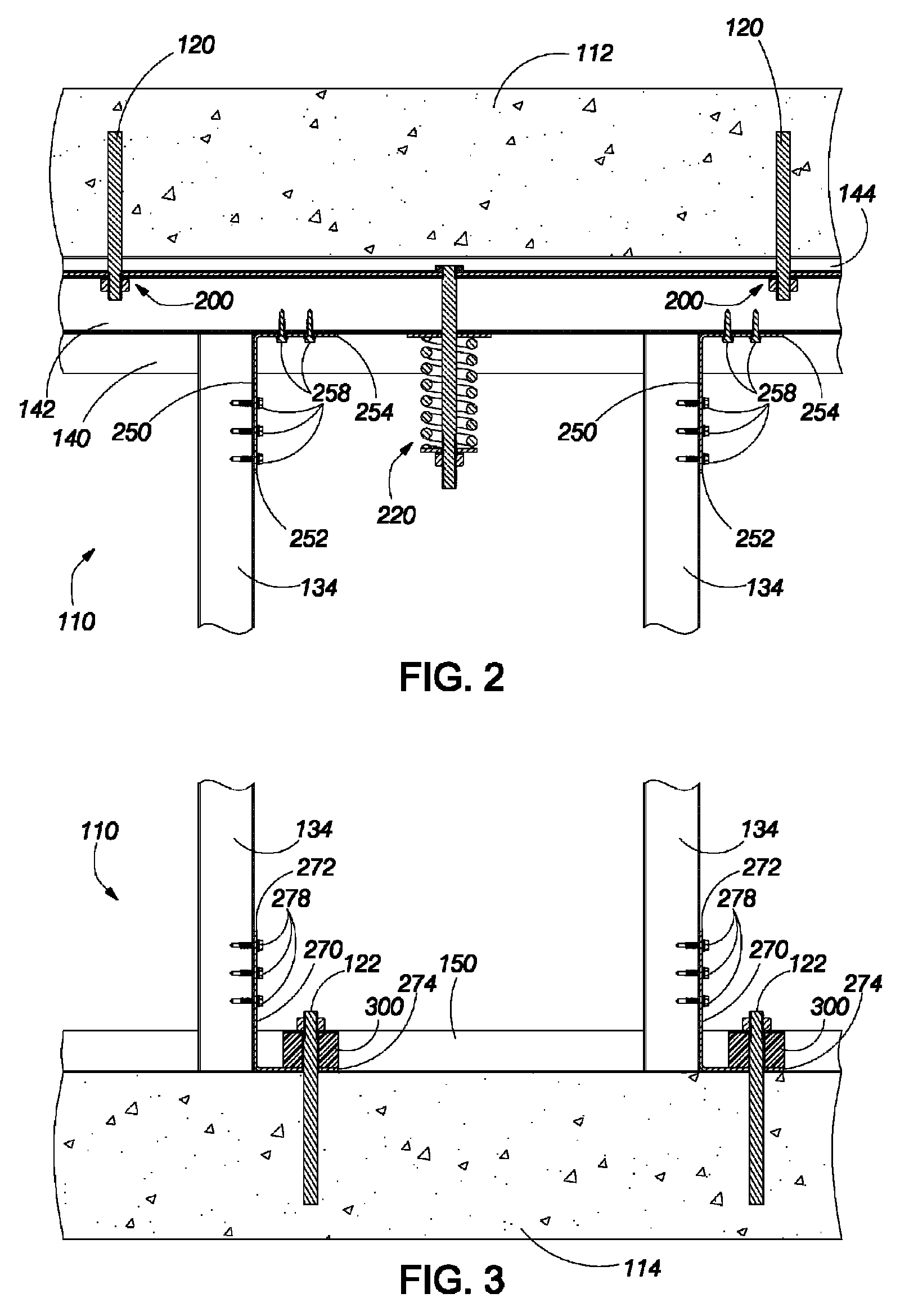
[0040]FIG. 1 illustrates a perspective view of a blast wall 100. The blast wall comprises a blast wall assembly 110 installed between an upper header 112 and a lower footer 114. In the illustrated embodiment, the header and the footer comprise concrete; however, the header, the footer or both may comprise other suitable materials. In the illustrated embodiment, the blast wall assembly is secured to the header and the footer by a plurality of upper anchor bolts 120 (one of which is shown in the broken section of the header) and a plurality of lower anchor bolts 122 (one of which is shown in the broken section of the footer). In the illustrated embodiment, the upper anchor bolts are advantageously spaced apart by approximately 24 inches and the lower anchor bolts are advantageously spaced apart by 16 inches. In other configurations, the distances between the anchor bolts may be different.

[0041]As further shown in FIG. 1, the blast wall assembly 110 comprises a plurality of inner blast...


PUM


Abstract

A wall system protects a building structure from pressure caused by explosive blasts. The wall system includes vertical studs. Outer blast wall panels and inner blast wall panels are secured to the opposing sides of the vertical studs. An upper mounting system is attached to the building structure. An upper mounting system includes a fixed track, a movable mounting track, and an energy absorbing system that flexibly couples the movable mounting track to the fixed track. The upper ends of the vertical studs are attached to movable mounting track. A lower mounting system includes a mounting track that aligns the lower ends of the vertical studs. A respective attachment clip is attached to a lower portion of vertical stud. Each attachment clip is attached to the building structure with an energy absorption pad that resists vertical and lateral movement of lower end of the respective vertical stud.

Description

BACKGROUND OF THE INVENTION[0001]1. Field of the Invention[0002]The present invention is generally in the field of protective wall structures for buildings, and, more particularly, is in the field of blast resistant walls.[0003]2. Description of the Related Art[0004]Current existing blast resistant wall assemblies attempt to resist the extreme forces generated by explosives with massively heavy and very costly components. The wall components endeavor to remain in place when impacted by a blast wave. If the wall components fail, the components are propelled into the interior space of the structure to damage equipment and harm people that the wall components are intended to protect.SUMMARY OF THE INVENTION[0005]A blast wall assembly and the components described herein form an integrated system that effectively absorbs blast energy. Unlike conventional systems, the components of the blast wall assembly function in a manner similar to highway “crumple zones” by absorbing the energy gene...

Claims


Application Information

Patent Timeline
Patent Type & Authority Patents(United States)
IPC IPC(8): E04B1/00
CPCE04H9/10
Inventor SWARTZ, ALLAN J.KULPA, GREGORYELLIOTT, A. CARLETON
Owner SPECIALTY HARDWARE LLC
Why Eureka
Try Eureka