Eureka AIR delivers breakthrough ideas for toughest innovation challenges, trusted by R&D personnel around the world.

Pendulous accelerometer with balanced gas damping

a pendulous accelerometer and gas damping technology, applied in the direction of speed/acceleration/shock measurement, measurement devices, instruments, etc., can solve the problems of reducing sensitivity, reducing resonant frequency, and reducing the total mass of the plate, so as to reduce the overall chip size, balanced gas damping, and high sensitivity

Inactive Publication Date: 2011-12-20
ROSEMOUNT AEROSPACE
View PDF35 Cites 39 Cited by
  • Summary
  • Abstract
  • Description
  • Claims
  • Application Information

AI Technical Summary

Benefits of technology

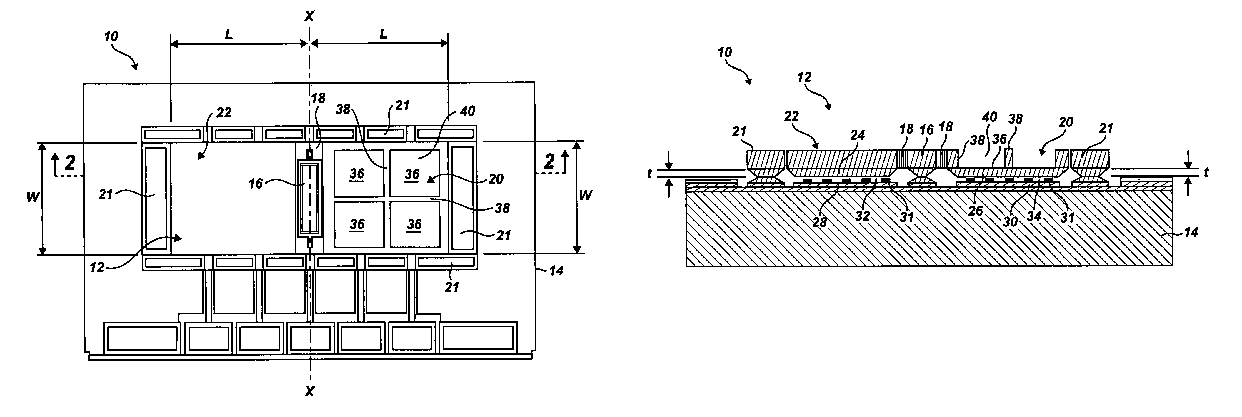
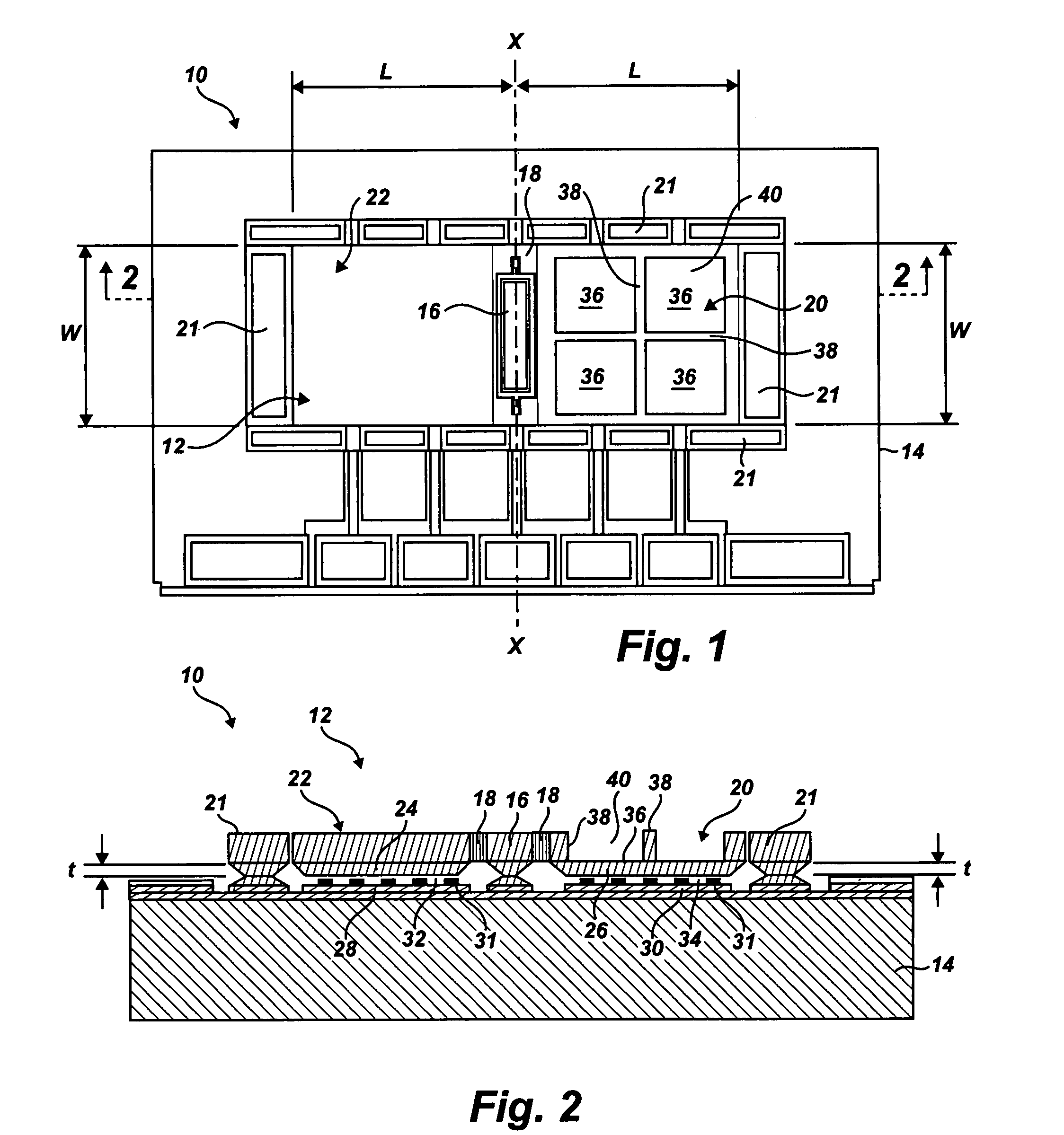
The accelerometer provides a symmetric plate area having an asymmetric plate mass, which allows for the overall chip size to be reduced while maintaining balanced gas damping and high sensitivity. The accelerometer includes a substrate having a substantially planar upper surface and a sensing plate having a central anchor portion supported on the upper surface of the substrate to define a hinge axis. The sensing plate includes a solid proof mass on a first side of the central anchor portion and a substantially hollow proof mass on a second side of the central anchor portion. The solid proof mass has a first lower surface with a first electrode element thereon, and the substantially hollow proof mass has a second lower surface with a second electrode element thereon.

Problems solved by technology

The resolution of high-performance accelerometers has been limited by thermomechanical Brownian noise of the sensor, which is dictated by the damping coefficient and the mass of the structure, as well as by the readout electronics.
However, increasing the center mass offset by the asymmetric shaping methods mentioned above may result in an increase in total mass of the plate, which leads to reduced resonant frequency and decreased sensitivity.
Increasing the center mass offset by asymmetric shaping may also result in a sacrifice of some of the dynamic g-range, which is defined by the separation distance between a stationary sensing element and the pendulous acceleration sensing plate.
However, extending one side of the plate may lead to unbalanced gas damping, which results in performance degradation.
However, such perforations also reduce the center mass offset and so reduces the sensitivity.
Additionally, extending one side of the plate may result in an increase of the overall chip size.
However, the extended portion of the plate increases the dimension of the overall chip size, leads to unbalanced gas damping, and reduces the resonant frequency of the rotational structure, which again results in a decrease in the performance of the accelerometer.

Method used


Image

  • Pendulous accelerometer with balanced gas damping
  • Pendulous accelerometer with balanced gas damping
  • Pendulous accelerometer with balanced gas damping

Examples


Embodiment Construction

Reference will now be made in detail to the present preferred embodiments of a pendulous accelerometer, examples of which are illustrated in the accompanying drawings.

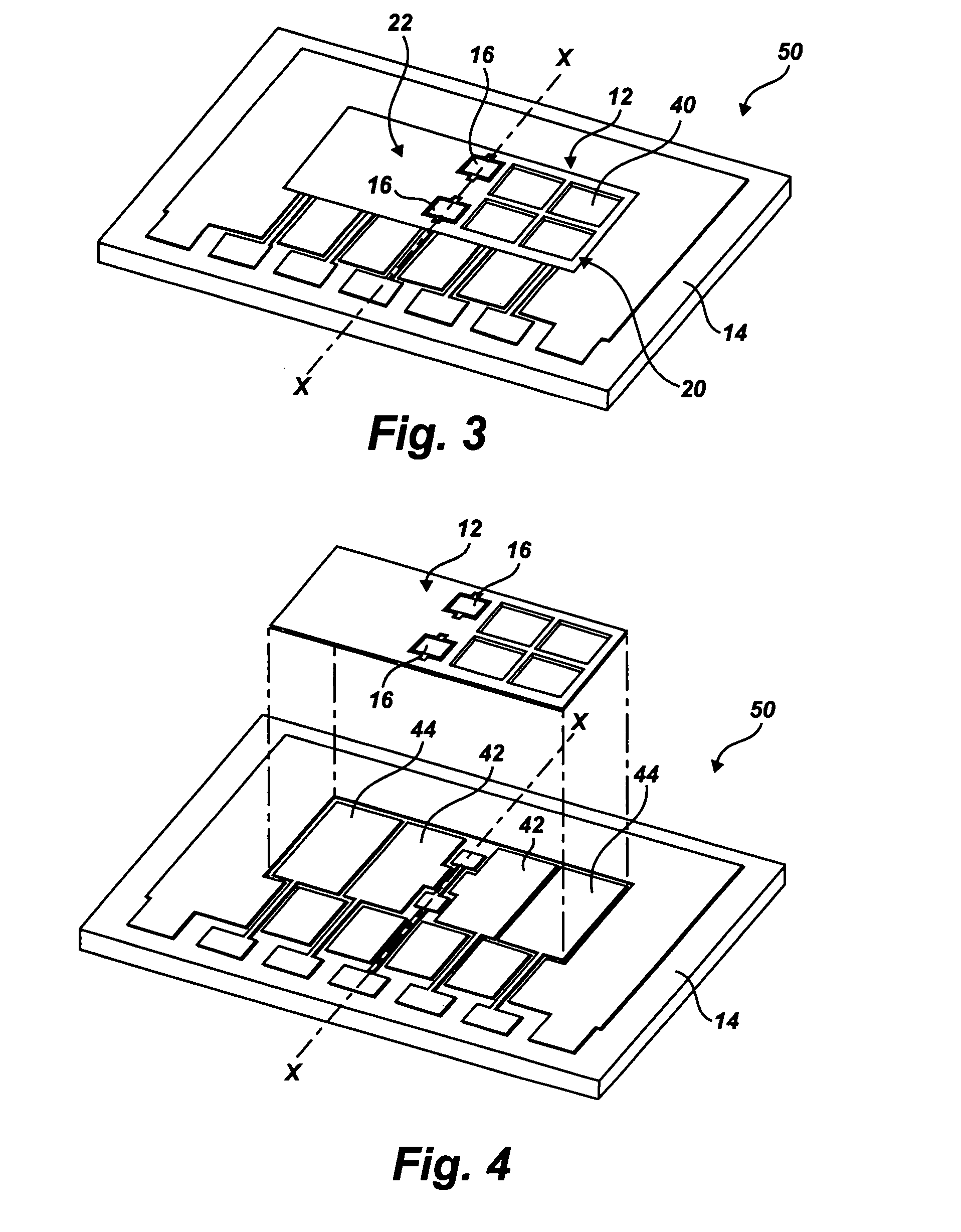
For purposes of explanation and illustration, and not limitation, a perspective view of an exemplary embodiment of the accelerometer is shown in FIGS. 1 and 2 and is designated generally by reference character 10.

Accelerometer 10 includes a sensing plate 12 and a substrate 14. Sensing plate 12 is attached to substrate 14 by one or more anchor portions 16 located near the center of the plate. Anchor portions 16 define a hinge axis x. Anchor portions 16 attach sensing plate 12 to substrate 14, allowing sensing plate 12 to rotate about hinge axis x.

In one exemplary embodiment, substrate 14 is made from a semiconductor such as silicon. In another exemplary embodiment, substrate 14 comprises a silicon on insulator (SOD) structure. Similarly, sensing plate 12 can also be made of a semiconductor such as silicon.

As shown in FI...


PUM


Abstract

A pendulous capacitive accelerometer including a substrate having a substantially planar upper surface with an electrode section, and a sensing plate having a central anchor portion supported on the upper surface of the substrate to define a hinge axis. The sensing plate includes a solid proof mass on a first side of the central anchor portion and a substantially hollow proof mass on a second side of the central anchor portion, providing for reduced overall chip size and balanced gas damping. The solid proof mass has a first lower surface with a first electrode element thereon, and the substantially hollow proof mass has a second lower surface with a second electrode element thereon. Both the solid proof mass and the hollow proof mass have the same capacitive sensing area. The sensing plate rotates about the hinge axis relative to the upper surface of the substrate in response to an acceleration.

Description

BACKGROUND OF THE INVENTION1. Field of the InventionThe present invention relates to accelerometers and other force sensing devices, and more particularly to capacitive pendulous accelerometers for measuring acceleration of an object.2. Description of Related ArtHigh performance accelerometers with near micro-gravity resolution, high sensitivity, high linearity, and low bias drift are needed for a wide variety of applications, especially aerospace applications such as inertial navigation systems, guidance systems, and air data measurement systems. The resolution of high-performance accelerometers has been limited by thermomechanical Brownian noise of the sensor, which is dictated by the damping coefficient and the mass of the structure, as well as by the readout electronics.Fabrication technology plays a critical role in ensuring that large mass, large capacitance, and small damping are simultaneously obtained, and that micro-gravity resolution is achieved. Previously, a number of h...

Claims


Application Information

Patent Timeline
Patent Type & Authority Patents(United States)
IPC IPC(8): G01P15/125
CPCG01P15/0802G01P15/125G01P15/131G01P2015/0831
Inventor GUO, SHUWEN
Owner ROSEMOUNT AEROSPACE
Why Eureka
Eureka Blog
Learn More