Displacement measuring instrument and displacement measuring method

a technology of displacement measurement and displacement measurement, which is applied in the direction of instruments, measurement devices, interferometers, etc., can solve the problems of difficult to measure an object with sub-nanometer accuracy, reduced stability of light source, availability and safety of optical components, and complicated optical systems. achieve the effect of easy and accurate calculation in nanometers

Active Publication Date: 2011-12-20
MITUTOYO CORP
View PDF5 Cites 0 Cited by
  • Summary
  • Abstract
  • Description
  • Claims
  • Application Information

AI Technical Summary

Benefits of technology

[0014]In view of the above, an object of the invention is to provide a displacement measuring instrument and a displacement measuring method capable of simply and accurately measuring a displacement of an object in a narrow range.
[0046]K is a constant (referred to as an environmental factor constant) given by the refractive indexes of the laser beams and is determined by the measurement environmental factors such as temperature, atmospheric pressure, humidity and CO2 concentration. For example, K can be easily calculated by using a thermometer, barometer, hygrometer and CO2 concentration meter.
[0049]In the above-described displacement measuring instrument and displacement measuring method, K is approximately 4.2×10⁻⁶ in the air and sufficiently smaller than 1. Thus, even when the displacement D of the measurement reflector is extremely small, the displacement D is converted into the displacement l of the reference reflector to have a large value. By measuring the displacement l of the reference reflector in approximate 10 μm, for instance, the displacement D of the measurement reflector can be accurately measured in picometers. In other words, the displacement measuring instrument of the invention can be provided by a simple arrangement without using an X-ray having a short-wavelength or providing a large instrument including a complicated optical system and expensive optical components. Additionally, because laser beams in a visible region or in a near infrared region can be used, safety of the light source can be ensured. Further, because the light source emits laser beams having predetermined wavelengths, high stability of the wavelengths can be obtained without being affected by the dispersion of the laser beam in the optical components as in the wavelength variable laser. Furthermore, the displacement measurement can be accurately conducted in picometers as described above, thereby enhancing measurement accuracy in a narrow range.
[0051]According to the above arrangement, the reference displacement detector detects the displacement of the reference reflector based on the interference signal corresponding to the long-wavelength laser beam. Here, the long-wavelength laser beam irradiated to the measurement optical path is split by the measurement light splitter and is reflected by the long-wavelength reflector so as not to reach the measurement reflector. In other words, the displacement l of the reference reflector can be easily and accurately calculated in nanometers using the wavelength λ1 of the long-wavelength laser beam and the refractive index n1 of the long-wavelength laser beam based on the above formula (1).

Problems solved by technology

Accordingly, it is difficult to measure an object with sub-nanometer accuracy.
However, stability of a light source and availability and safety of optical components are reduced when light in an ultraviolet region or an X-ray region having a wavelength shorter than that in a visible range is used, and the instrument is enlarged.
However, an optical system becomes complicated and light quantity is reduced because of the amplified optical path length.
Further, high stability of the wavelength is hardly obtained.
Thus, it is difficult for a laser interferometer having a simple arrangement to enhance sub-nanometer measurement accuracy in a narrow measurement range of a few micrometers.

Method used


Image

  • Displacement measuring instrument and displacement measuring method
  • Displacement measuring instrument and displacement measuring method
  • Displacement measuring instrument and displacement measuring method

Examples


Embodiment Construction

)

[0063]A laser interferometric measuring instrument will be exemplarily described as a displacement measuring instrument according to an exemplary embodiment of the invention with reference to the attached drawings.

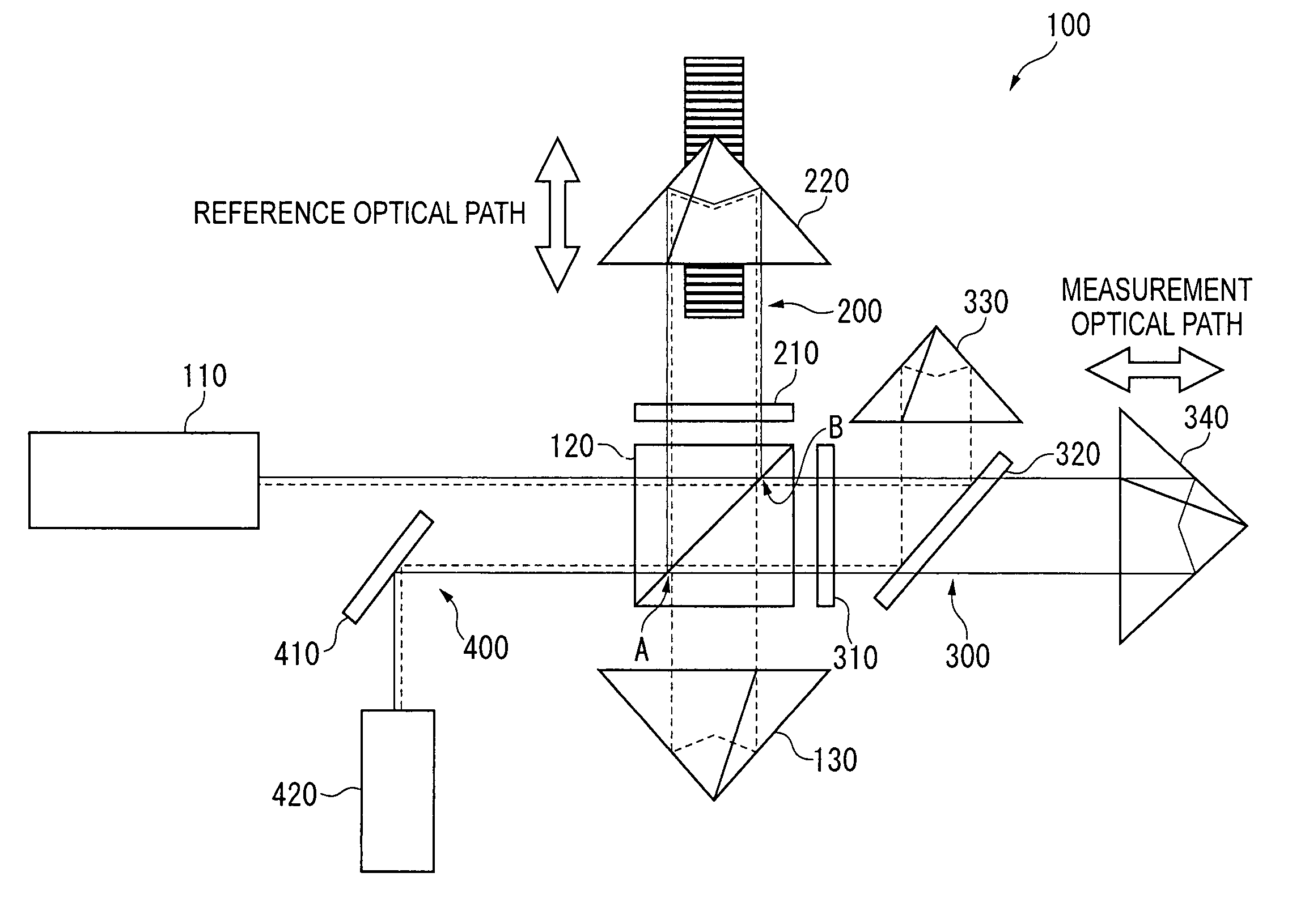
[0064]FIG. 4 is a block diagram schematically showing a laser interferometric measuring instrument according to the exemplary embodiment of the invention.

[0065]A laser interferometric measuring instrument 1 measures, for example, a displacement D of a target object 3 on a stage 2 as shown in FIG. 4. The laser interferometric measuring instrument 1 is incorporated in a machine tool for producing precision components, a highly accurate measuring instrument, a microscopic profile measuring instrument or the like to accurately measure a displacement of a target object in 10−12 m. In this exemplary embodiment, the laser interferometric measuring instrument 1 for measuring the displacement of the target object 3 provided on the stage 2 is exemplarily explained. However, the las...


PUM


Abstract

A laser interferometric measuring instrument includes: a light source that emits a laser beam of 1064 nm and another laser beam of 532 nm; a polarizing beam splitter; a dichroic mirror that splits a long-wavelength laser beam provided in a measurement optical path; a long-wavelength corner cube that reflects the split laser beam; a measurement corner cube that is displaceable along the measurement optical path; a reference corner cube that is displaceable along a reference optical path; a optical path changing unit that changes an optical path length of the long-wavelength laser beam; a phase detector that outputs interference signals; a sum signal computer that calculates a sum signal; a displacement controller that displaces the reference corner cube so as not to change a phase of the sum signal; a reference displacement detector that detects a displacement of the reference corner cube; and a measurement displacement computer that calculates a displacement of the measurement corner cube.

Description

[0001]The entire disclosure of Japanese Patent Application No. 2008-200023, filed Aug. 1, 2008, is expressly incorporated by reference herein.BACKGROUND OF THE INVENTION[0002]1. Field of the Invention[0003]The present invention relates to a displacement measuring instrument and a displacement measuring method of measuring a displacement of an object.[0004]2. Description of Related Art[0005]A laser interferometer capable of setting alignment freely and reducing Abbe errors as compared to a solid scale has been typically known (for instance, see Document 1: JP-A-5-272913).[0006]In the laser interferometer disclosed in Document 1, 1.06 μm YAG laser and its second harmonic are emitted from a light source to be incident on a beam splitter after their polarization states are adjusted by a half-wave plate. A laser beam reflected by the beam splitter is reflected by a reference mirror and a laser beam passed through the beam splitter is reflected by a probe mirror, so that these reflected b...

Claims


Application Information

Patent Timeline
Patent Type & Authority Patents(United States)
IPC IPC(8): G01B9/02
CPCG01B9/02G01B9/0207G01B2290/70G01B2290/15G01B2290/60
Inventor MIYATA, KAORU
Owner MITUTOYO CORP
Why Eureka
Try Eureka