
Lighting protection system for wind generators

a technology of wind generators and protection systems, applied in the installation of lighting conductors, connection to earth, machines/engines, etc., can solve the problems of high probability of attracting lightning, difficult replacement, and complicated construction, and achieve the effect of easy maintenan

Active Publication Date: 2011-12-20
GAMESA INNOVATION & TECH SA
View PDF14 Cites 10 Cited by
  • Summary
  • Abstract
  • Description
  • Claims
  • Application Information

AI Technical Summary

Benefits of technology

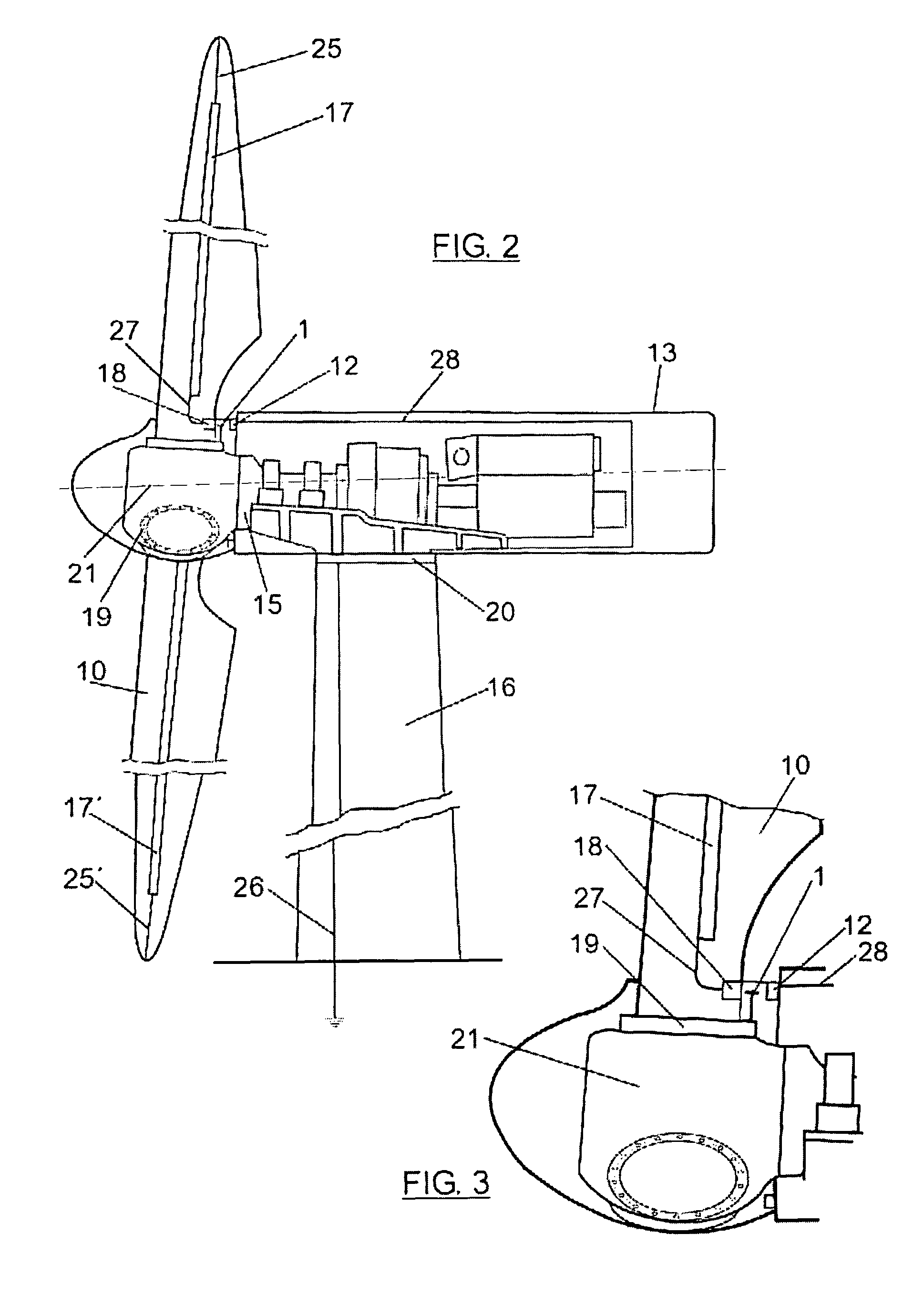
[0008]In order to overcome the disadvantages in the state of the art, a new, more efficient and safer lightning transmission system has been designed whereby all of the lightning that impacts on the tip of one of the wind turbine blades is routed to earth through the nacelle structure, thus preventing it from passing through the blade bearings and the main shaft. In addition, this solution is easy to maintain and does not affect wind turbine operation.
[0012]The complexity of the invention lies in the passing of the lightning from a mobile part (rotor) to another fixed part (nacelle), given that it is essential to prevent any contact between them in order to decrease wear or risk of damage to the parts. With this invention, a distance between the lightning transmission element in relation to the root blade and the gutter is guaranteed to be between 8 and 15 mm at all times, although the range of acceptable values is greater (between 0.5 to 30 mm). This separation is sufficient to prevent any collisions between the lightning transmission element and other parts of the wind turbine which have relative movement in relation to said lightning transmission element, whilst also being sufficiently small to guarantee the flashover in the event of a lightning impact.
[0013]Another advantage of the system of this invention is that it reduces the damage to the gutter and blade root materials, during discharges of both long and short duration; whilst at the same time, it also prevents the discharge from reaching the control cabinet of the hub as it suppresses the passage of current through the bearings. Another advantage of this invention is the simplicity with which it can be replaced in the event of damage after various lightning discharges.

Problems solved by technology

The sitting of wind turbines in said exposed areas and the geometry of the wind turbines themselves means that there is a high probability of attracting lightning.
Discharging lightning using this route causes damage to the bearings and the main shaft, thus leading to alternative solutions being sought.
In addition, the resistance is located in a place that is difficult to access and is therefore difficult to replace in the event that it is damaged by lightning.
Other systems are known, such as the system detailed in document EP 0718495, that creates a structure outside the nacelle which complicates construction and negatively affects the aerodynamics of the wind turbine.

Method used


Image

  • Lighting protection system for wind generators
  • Lighting protection system for wind generators
  • Lighting protection system for wind generators

Examples


Embodiment Construction

[0023]Here follows a brief description of an embodiment of the invention provided for illustration purposes, thus the invention is not limited to said embodiment.

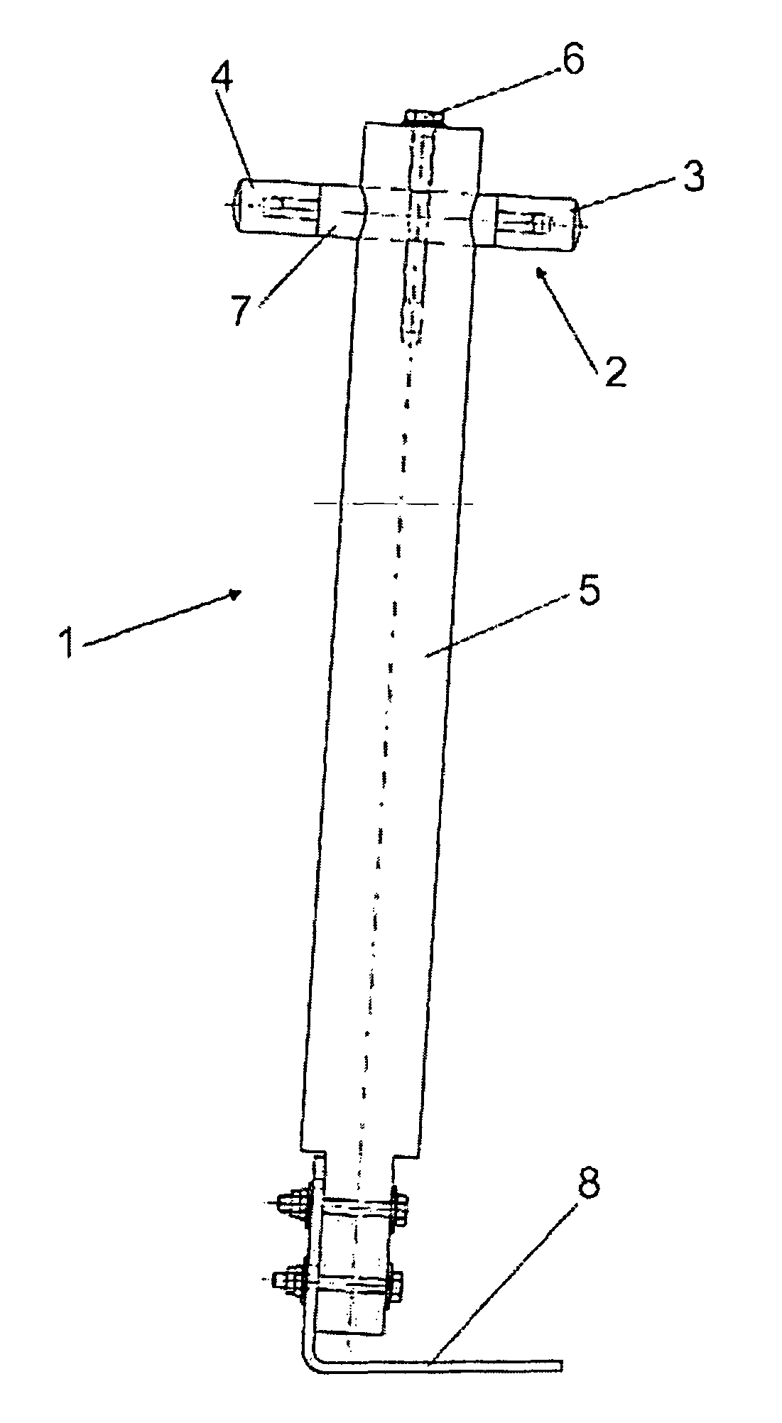
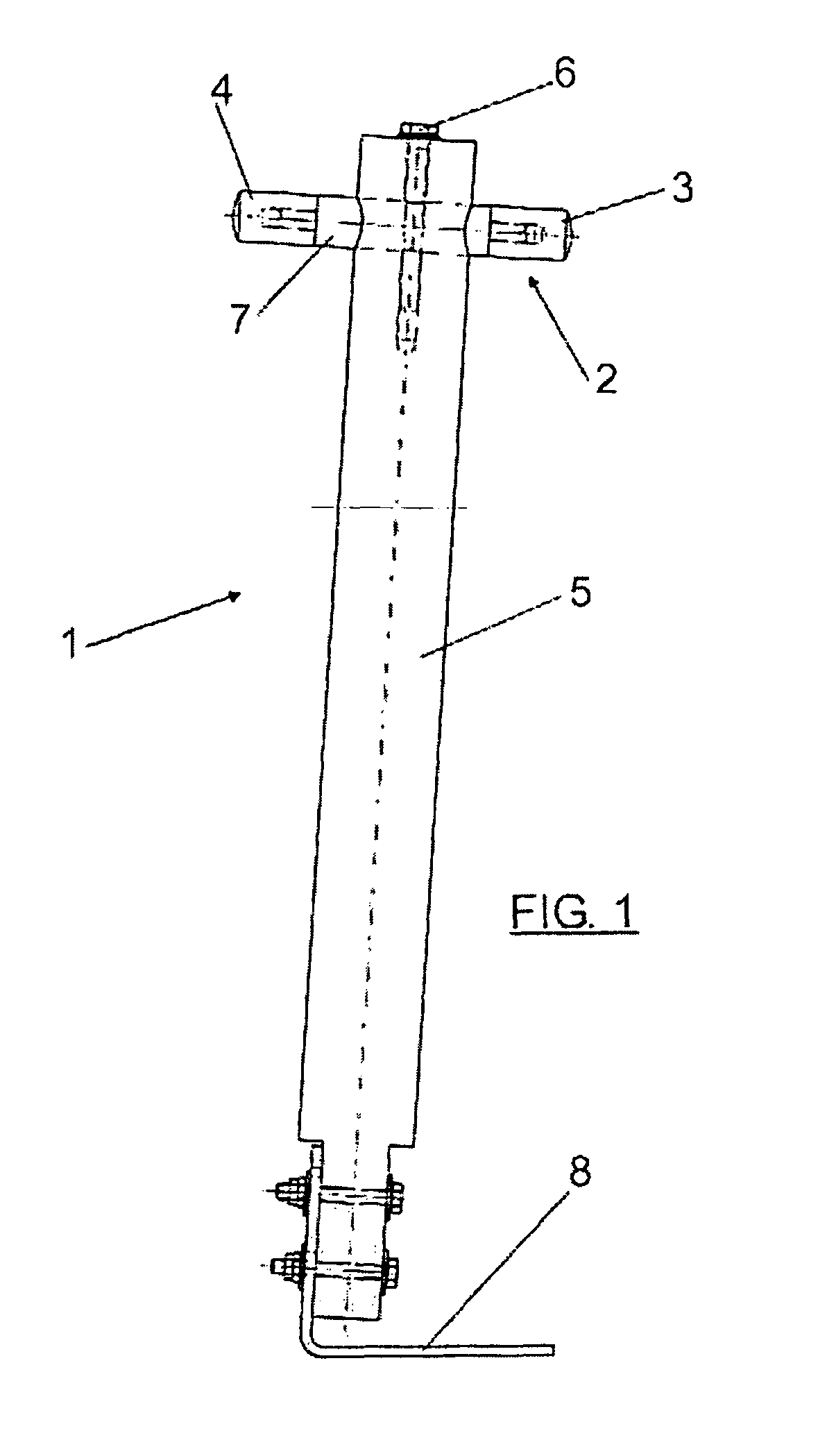
[0024]FIG. 1 shows a lightening transmission element (1) formed by two bars (2, 5) crossed in a T and a base plate (8). A first bar (2) of conductor material is situated perpendicularly to a second bar (5) of insulating material in the proximity of the upper end of said second bar (5), a base plate (8) is fixed on one side to the bottom end of the bar (5) and on the other side to a wind turbine blade bearing (19).

[0025]The first bar (2) is formed by three parts: a first end (4), a second end (3) and a central part (7). The two ends (3, 4) can be removed from the central part (7) in order to be replaced in the event that they are affected by a lightning discharge. For this purpose there are threaded holes inside both ends (3, 4) to enable connection to threaded shafts joined to the central part (7). Other fixture methods may...


PUM


Abstract

The invention relates to a lightning transmission element (1) which is fixed to a hub (21) of a wind generator and which is formed by a first conductor bar (2) which is fixed to a second insulating bar (5). According to the invention, a first end (4) of the lightning transmission element (1) is positioned opposite a metal strip (18) that is disposed at the root of each blade (10) of the wind generator at a first distance which enables a flashover of incident lightning at a point on a blade (10) of the wind generator, while a second end (3) thereof is positioned opposite a gutter (12) of a nacelle (13) of the wind generator at a second distance which enables a lightning flashover. The lightning is conveyed from the point on the blade (10) at which it is incident thereon to the earth through a series of conduction means including the lightning transmission element (1), said means preventing the lightning from striking the sensitive parts of the wind generator.

Description

FIELD OF THE INVENTION[0001]This invention refers to a non-contact lightning transmission system configured to be installed on a wind turbine. This system enables the vital parts of the wind turbine to be protected against lightning, thus reducing the need for wind turbine maintenance.STATE OF THE ART[0002]The sector to which the technique of the invention belongs is that of wind turbine lightning protection.[0003]Wind turbines used in the recovery of wind energy need to be located in points that are unprotected from meteorological conditions in order to take full advantage of the wind. The sitting of wind turbines in said exposed areas and the geometry of the wind turbines themselves means that there is a high probability of attracting lightning.[0004]One system used to protect the components of the wind turbine against lightning impacts consists of directing the discharge from the tip of the blade to earth, by firstly using an internal cable that joins the tip of the blades with a...

Claims


Application Information

Patent Timeline
Patent Type & Authority Patents(United States)
IPC IPC(8): H01H47/00H05F3/00
CPCF03D1/065F03D11/0033H02G13/00H02G13/40H02G13/80Y02E10/722Y02E10/721F03D80/30Y02E10/72F03D80/00
Inventor LLORENTE GONZALEZ, JOSE IGNACIO
Owner GAMESA INNOVATION & TECH SA
Learn More