Solid electrolytic capacitor and method for manufacture thereof

a solid electrolytic capacitor and capacitor technology, applied in the direction of liquid electrolytic capacitors, casings/cabinets/drawers, electrical apparatus casings/cabinets/drawers, etc., can solve the problems of increased leakage current, increased leakage current, and decreased yield, so as to reduce the cost of solid electrolytic capacitors, suppress leakage current, and increase the thermal expansion coefficient

Active Publication Date: 2011-12-20
SAN DENSHI INDS
View PDF9 Cites 0 Cited by
  • Summary
  • Abstract
  • Description
  • Claims
  • Application Information

AI Technical Summary

Benefits of technology

[0015]An object of the present invention is to provide a solid electrolytic capacitor that contributes to suppressed leakage current and reduced cost, and to provide a method for manufacturing such a solid electrolytic capacitor.
[0023]With this structure, in a capacitor element, on a surface of an anode member formed of a metal or an oxide having a valve action, a dielectric member of an oxide coating or the like is formed, and on a surface of the dielectric member, a cathode layer formed of a solid electrolytic layer such as manganese oxide or organic electrically-conductive polymer is provided. Moreover, in the capacitor element, at one face, referred to as a terminal lead-out face, of the anode member, an anode wire is fitted by planting or welding. An anode terminal such as a lead frame is joined to the anode wire, and a cathode terminal such as a lead frame conductive to the cathode layer is provided. Around the capacitor element, a protective layer of resin is formed, and the protective layer and the anode wire are covered, from around, by resin harder than the protective layer. The protective layer has a larger linear expansion coefficient than the packaging member, and the mass of the packaging member in an anode terminal-side part is 50% or more of the total mass of the packaging member and the protective layer. The shock resulting from resin injection at the time of the transfer-molding of the packaging member, the contraction of the packaging member during its hardening, and the expansion and contraction of the packaging member at the time of the soldering of the anode and cathode terminals are absorbed by the elasticity of the soft protective layer. Moreover, since there is less of the protective layer around the anode wire compared with the packaging member there, it is possible to prevent rupturing of the packaging member resulting from thermal expansion of the protective layer at the time of the soldering of the anode and cathode terminals.
[0037]According to the present invention, the packaging member is formed of resin harder than the protective layer, the protective layer has a larger linear expansion coefficient than the packaging member, and the mass ratio of the packaging member relative to the total mass of the packaging member and the protective layer between the terminal lead-out face, at which the anode wire is led out, and the exterior face of the packaging member opposite the terminal lead-out face is 50% or more. Thus, it is possible to reduce the cost of the solid electrolytic capacitor. Moreover, the contraction of the packaging member during hardening and the expansion and contraction of the packaging member at the time of the soldering of the anode and cathode terminals are absorbed by the elasticity of the protective layer. Furthermore, the shock resulting from resin injection at the time of the transfer-molding of the packaging member is absorbed by the soft protective layer. Thus, it is possible to suppress leakage current caused by mechanical stress on the capacitor element. In addition, in a terminal lead-out face-side part, while the protective layer and the packaging member covering the anode wire are provided over a wide area, there is less of the protective layer, which has a larger thermal expansion coefficient. Thus, it is possible to prevent rupturing of the packaging member resulting from thermal expansion of the protective layer at the time of soldering.

Problems solved by technology

Exposing the capacitor element 10 to mechanical stress results in significantly increased leakage current.
If, however, the damage at the time of molding is severe, repair by aging is difficult, leading to diminished yields due to short circuiting and unduly large leakage current.
This causes the capacitor element 10 of the solid electrolytic capacitor 1, which has undergone an aging process, to receive mechanical stress again, leading to the problem of increased leakage current.
Inconveniently, however, according to the solid electrolytic capacitor 1 disclosed in JP-A-H5-136009 mentioned above, the silicone resin or the like used for the protective layer 2—a low-stress one which in addition has a smaller linear expansion coefficient than the hard resin such as epoxy resin forming the packaging member 3—is very expensive.
This leads to the problem of the solid electrolytic capacitor 1 requiring an increased cost.

Method used


Image

  • Solid electrolytic capacitor and method for manufacture thereof
  • Solid electrolytic capacitor and method for manufacture thereof
  • Solid electrolytic capacitor and method for manufacture thereof

Examples


Embodiment Construction

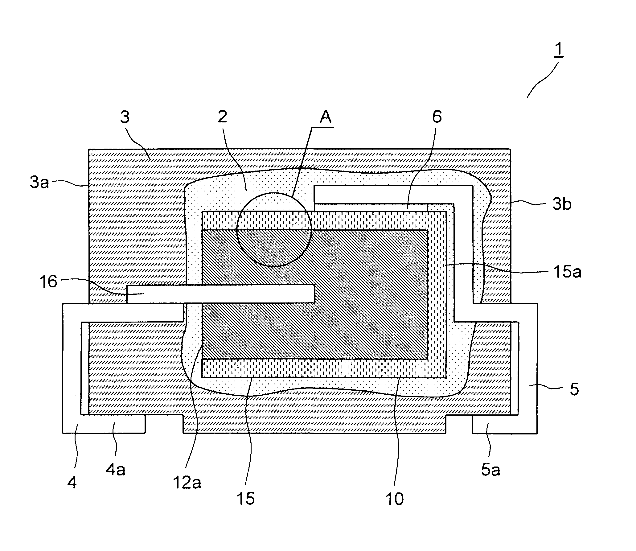
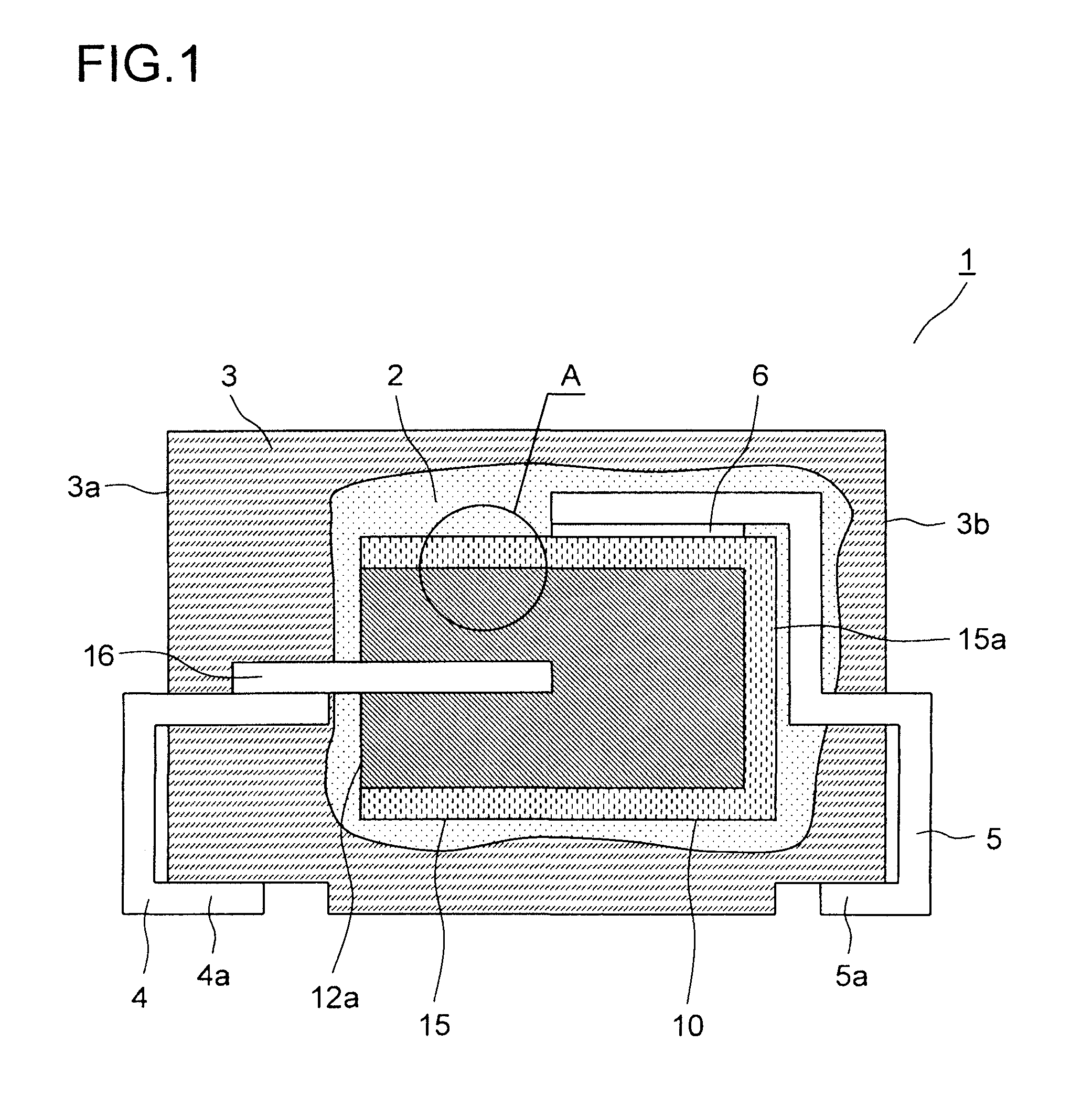
[0044]Embodiments of the present invention will be described below with reference to the accompanying drawings. For convenience' sake, such parts as find their counterparts in the conventional examples shown in FIGS. 4 and 5 described earlier are identified by common reference signs. FIG. 1 is a front sectional view of a solid electrolytic capacitor according to a first embodiment of the invention. FIG. 2 is an enlarged view of part A in FIG. 1. The solid electrolytic capacitor 1 has a capacitor element 10 covered by a protective layer 2 and by a packaging member 3.

[0045]In the capacitor element 10, a porous anode member 12 is formed by molding powder, having an anode wire 16 planted at one end, of a metal or oxide having a valve action—such as tantalum, niobium, and an oxide of niobium—into predetermined dimensions and then subjecting it to high-temperature vacuum sintering. In this way, at one face, referred to as a terminal lead-out face 12a, of the anode member 12, the anode wir...


PUM

PropertyMeasurementUnit
temperatureaaaaaaaaaa
viscosityaaaaaaaaaa
temperatureaaaaaaaaaa

Abstract

On a surface of an anode member 12 having a valve action, a cathode layer 14 is formed, and at a terminal lead-out face 12a at one end of the anode member 12, an anode wire 16 is led out of it; thus a capacitor element 10 is formed. An anode terminal 4 is joined to the anode wire 16. A cathode terminal 5 is joined to the cathode layer 14. A protective layer 2 of resin covers part or all of the capacitor element 10. A packaging member 3 of resin harder than the protective layer 2 covers around the capacitor element 10 including the protective layer 2 and the anode wire 16 to form a package. The protective layer 2 has a larger linear expansion coefficient than the packaging member 3. The mass ratio of the packaging member 3 to the total mass of the packaging member 3 and the protective layer 2 between the terminal lead-out face 12a and the exterior face of the packaging member 3 opposite the terminal lead-out face 12a is 50% or more.

Description

[0001]This application is based on Japanese Patent Application No. 2009-246691 filed on Oct. 27, 2009, the contents of which are hereby incorporated by reference.BACKGROUND OF THE INVENTION[0002]1. Field of the Invention[0003]The present invention relates to a solid electrolytic capacitor in which a capacitor element having a cathode layer formed on a surface of an anode member having a valve action is covered by resin, and also relates to a method for manufacturing such a solid electrolytic capacitor.[0004]2. Description of Related Art[0005]A conventional solid electrolytic capacitor is disclosed in JP-A-2005-45235. FIG. 4 is a front sectional view of that solid electrolytic capacitor. The solid electrolytic capacitor 1 has a capacitor element 10 in which a surface of an anode member molded of a valve-action metal is covered with a cathode layer formed of a solid electrolytic layer. Around the cathode layer, a cathode draw-out layer 15 is formed. At one face of the anode member, an...

Claims


Application Information

Patent Timeline
Patent Type & Authority Patents(United States)
IPC IPC(8): H01G9/04
CPCH01G9/012H01G9/10H01G9/15H01G9/08H01G9/0425H01G9/052Y10T29/417Y10T29/41
Inventor TAKETANI, YUTAKAHASABA, YOSHIAKISAKAMAKI, MAKOTOITO, TADAHITO
Owner SAN DENSHI INDS
Why Eureka
Try Eureka