Anti-roping device for pulverized coal burners

a technology of anti-roping device and pulverized coal, which is applied in the direction of mechanical equipment, lighting and heating equipment, combustion types, etc., can solve the problems of inefficient combustion, non-uniform coal particle distribution, and various technical problems of operation and maintenance of coal systems, and achieve the effect of improving particle distribution

Active Publication Date: 2011-12-27
BABCOCK POWER SERVICES
View PDF29 Cites 4 Cited by
  • Summary
  • Abstract
  • Description
  • Claims
  • Application Information

AI Technical Summary

Benefits of technology

The subject invention is directed to a new and useful orifice plate for improving particle distribution within coal piping systems of pulverized coal burners. The orifice plate includes a plate body defining a central orifice therethrough bounded by an inner periphery of the plate body. The plate body is configured and adapted to be affixed between end flanges of adjacent pipes in a coal piping system so as to generally align the central orifice with an internal flow passage through the coal piping system. Flow disruption features are defined in the inner periphery of the plate body. The flow disruption features are configured and adapted to disrupt a flow of air and particles flowing through the central orifice to provide a more uniform distribution of particles downstream of the plate body than upstream.

Problems solved by technology

As the coal particles travel in the air flow through the piping system, bends in the piping and the pipe geometry in general tend to cause non-uniform coal particle distribution.
Coal roping causes various technical problems for operation and maintenance of coal systems.
The poor distribution of coal particles can extend into the combustion zone, where localized imbalances in the fuel / air mixture tend to cause inefficient combustion and elevated emissions of NOX, CO, and other pollutants.
It can also cause elevated levels of unburned carbon in the fly ash, which will lower combustion efficiency.
Also, the highly abrasive nature of the coal rope impacting and scrubbing components of the coal piping and burning system causes extensive erosion of pipes and other components in the system, leading to frequent need for inspection, repairs, and replacement of parts.
If inspections, repairs and replacements are not performed in a timely manner, there is an elevated chance that abrasion from coal roping will cause expensive or dangerous failures of key components.
Moreover, the length of the diffuser, the multiple collision-style deflector rings and diffuser bars lead to inevitable pressure loss for the piping system.

Method used


Image

  • Anti-roping device for pulverized coal burners
  • Anti-roping device for pulverized coal burners
  • Anti-roping device for pulverized coal burners

Examples


Embodiment Construction

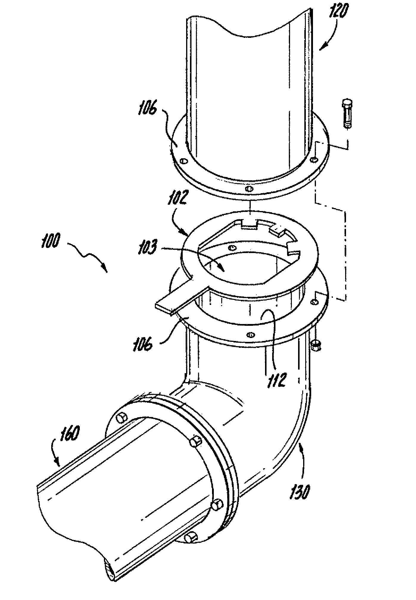
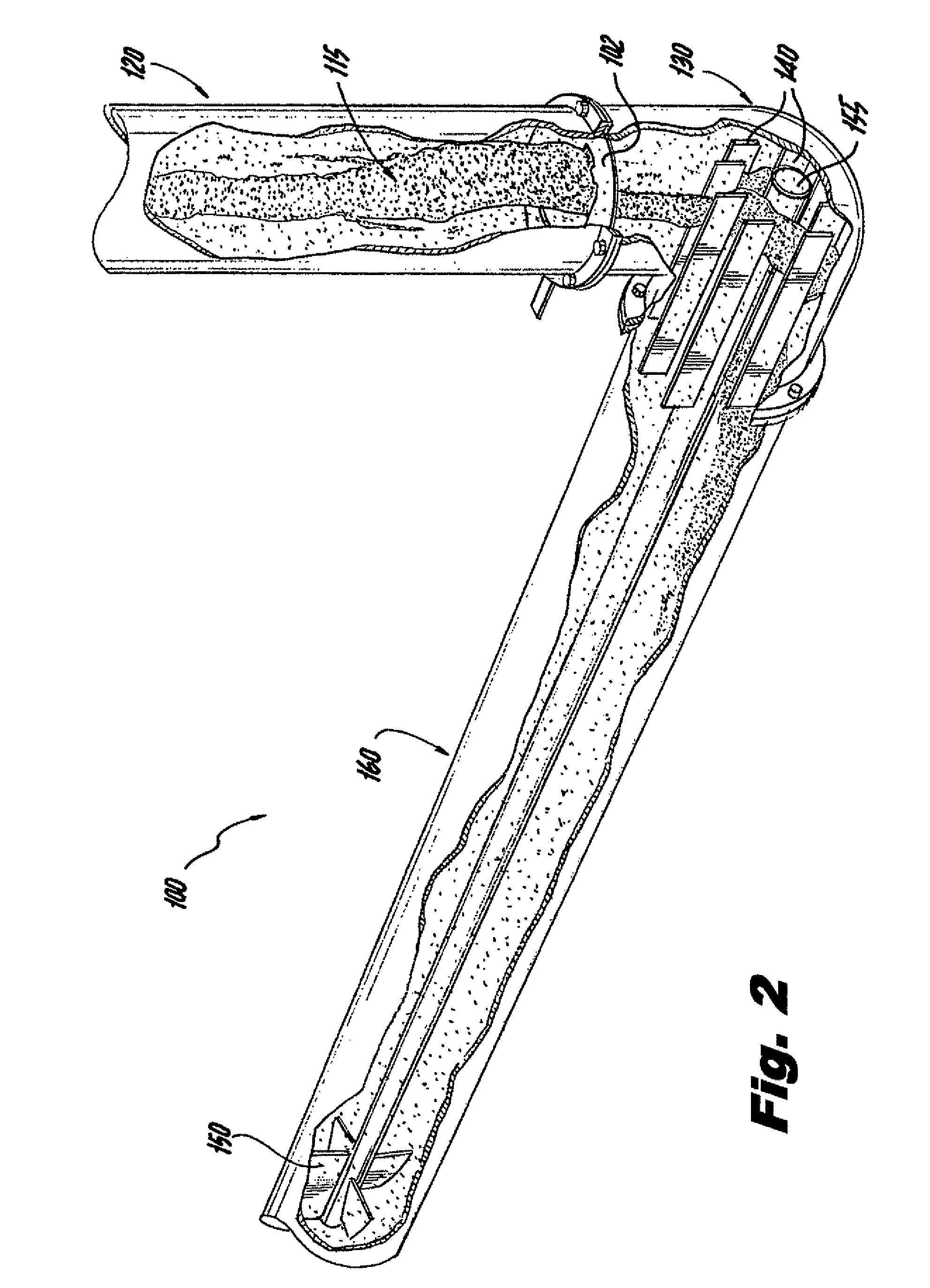
Reference will now be made to the drawings wherein like reference numerals identify similar structural features or aspects of the subject invention. For purpose of explanation and illustration, and not limitation, a partial view of an exemplary embodiment of the system in accordance with the invention is shown in FIG. 2 and is designated generally by reference character 100. Other embodiments of an orifice plate in accordance with the invention, or aspects thereof, are provided in FIGS. 3-6, as will be described. The system of the invention can be used in a variety of coal systems to provide improved coal particle distribution supplied to coal burners.

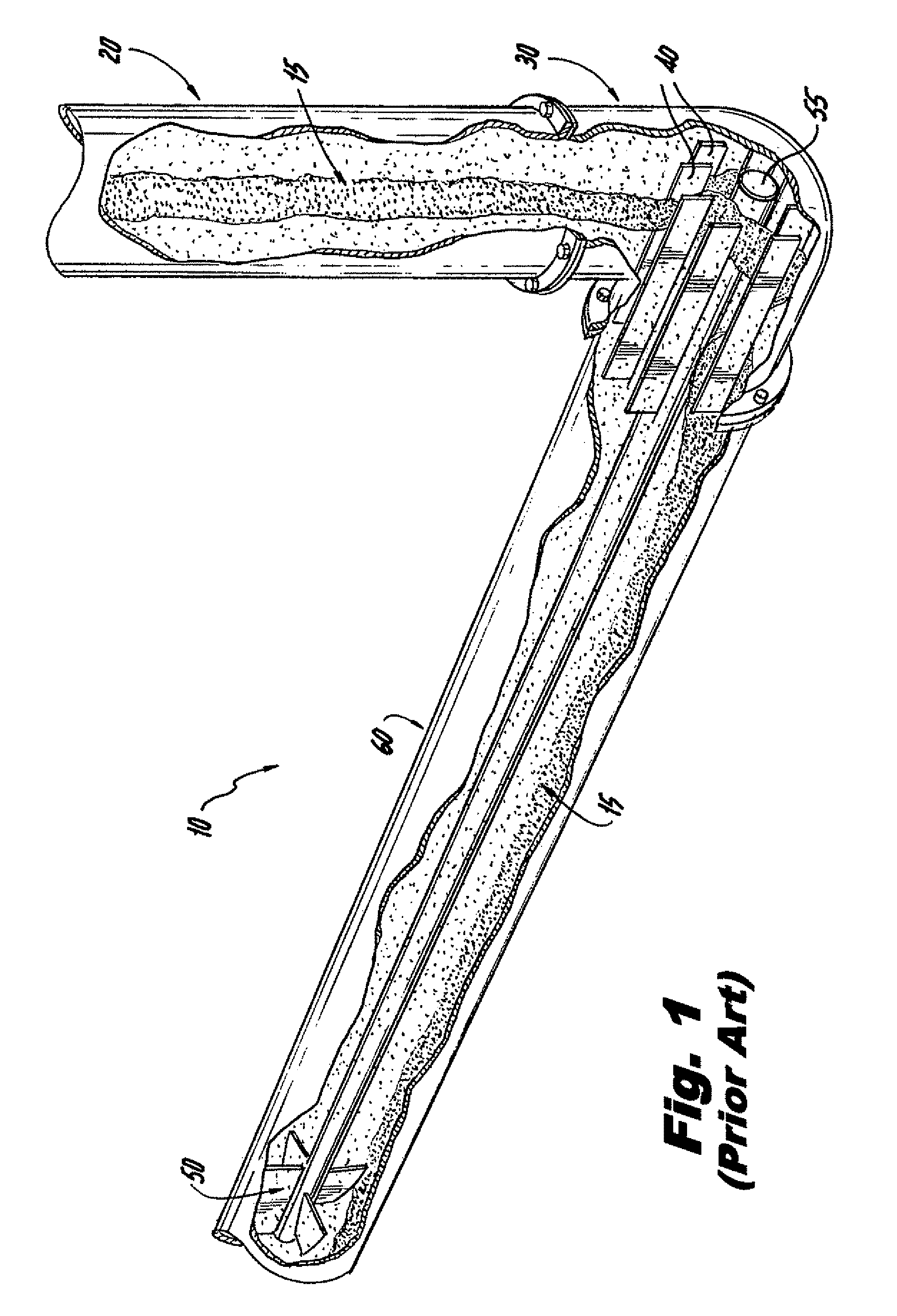
FIG. 1 shows a portion of an exemplary coal piping system 10 in a cut away perspective view with a representation of coal particles flowing therethrough. A coal rope 15 runs from upstream pipe 20, through elbow 30 and coal head vanes 40, to coal spreader 50 in downstream pipe 60, which incorporates a coal nozzle, just upstream of a bur...


PUM


Abstract

An orifice plate for improving particle distribution within a coal piping system includes a plate body defining a central orifice therethrough bounded by an inner periphery of the plate body. The plate body is configured and adapted to be affixed between end flanges of adjacent pipes in a coal piping system so as to generally align the central orifice with an internal flow passage through the coal piping system. Flow disruption features are defined in the inner periphery of the plate body. The flow disruption features are configured and adapted to disrupt a flow of air and particles flowing through the central orifice to provide a more uniform distribution of particles downstream of the plate body than upstream.

Description

BACKGROUND OF THE INVENTION1. Field of the InventionThe present invention relates to pulverized coal burners, and more particularly, to systems for delivering pulverized coal to coal fired burners.2. Description of Related ArtA variety of devices and methods are known in the art for delivering pulverized coal to coal fired burners. Of such devices, many are directed to improving particle distribution within coal piping systems for delivering coal to be combusted.Coal powered plants require an efficient means of supplying coal as fuel to produce heat power. Raw coal is typically pulverized in a coal pulverizer or mill to produce small coal particles or coal dust. The pulverized coal must then be delivered to a furnace or burner where it can be used for combustion. This is typically done with a coal piping system that utilizes air flows to transport pulverized coal particles from the mill or pulverizer to a nozzle where coal particles are injected into the coal burner or furnace. As t...

Claims


Application Information

Patent Timeline
Patent Type & Authority Patents(United States)
IPC IPC(8): F23D1/00F23K1/00
CPCF15D1/04F23K3/02F23D2201/20
Inventor COURTEMANCHE, BONNIEZARNESCU, VLADPENTERSON, CRAIG A.
Owner BABCOCK POWER SERVICES
Why Eureka
Try Eureka