Lighting device employing a light guide plate and a plurality of light emitting diodes

a light guide plate and light-emitting diode technology, applied in lighting and heating apparatus, planar/plate-like light guides, instruments, etc., can solve the problems of degrading the lumen efficiency of such a lighting device, insufficient light of a single led, etc., and achieve the effect of improving the lumen efficiency

Inactive Publication Date: 2011-12-27
KONINK PHILIPS ELECTRONICS NV
View PDF14 Cites 5 Cited by
  • Summary
  • Abstract
  • Description
  • Claims
  • Application Information

AI Technical Summary

Benefits of technology

[0006]It is an object of the present invention to overcome or at least alleviate this problem, and to provide a lighting device with improved lumen efficiency.
[0008]Because of the lens array, no or little light strikes the nearby holes. Therefore, the LEDs can be placed closer together and losses due to absorption or scattering at nearby LEDs in the lighting device are diminished. Overall, the luminous efficiency and power of the lighting device can be increased.
[0009]Preferably, the lens array comprises at least one row of positive lenses, to readily direct the light in the wanted directions. Also preferably, the lens pitch is about ½ of the LED pitch, which provides to a feasible design of the lighting device.
[0010]In one embodiment, the lens array is placed between one LED array and a reflective edge of the light guide plate such that light emitted by the LEDs in the array and reflected by the reflector is directed by the lens array to pass between the LEDs in the array. Thereby, losses due to absorption or scattering at adjacent LEDs / holes in the array are diminished, and the luminous efficiency of the lighting device is increased. To further boost these effects, the LEDs are preferably aligned with every second junction between two adjacent lenses in the lens array.
[0011]In another embodiment, the lens array is placed between a first LED array and a second LED array such that light emitted by the LEDs in the first array and passing the lens array is directed by the lens array to pass between the LEDs in the second array. Thereby, losses due to absorption or scattering at LEDs / holes in the nearby array are diminished, and the luminous efficiency of the lighting device is increased. To further boost these effects, the distance between the first LED array and the lens array and the distance between the second LED array and the lens array are preferably equal. Further, the LEDs of the first array may be aligned with the optical axes of every second lens in a row of the lens array while the LEDs of the second array may be aligned with the optical axes of every other second lens in the row of the lens array. Alternatively, the LEDs may be aligned with every second junction between two adjacent lenses in a row of the lens array.

Problems solved by technology

For many lighting applications, the light of a single LED is not sufficient, and light of multiple LEDs needs to be combined to form a light source.
Thus, the lumen efficiency of such a lighting device is degraded.

Method used


Image

  • Lighting device employing a light guide plate and a plurality of light emitting diodes
  • Lighting device employing a light guide plate and a plurality of light emitting diodes
  • Lighting device employing a light guide plate and a plurality of light emitting diodes

Examples


first embodiment

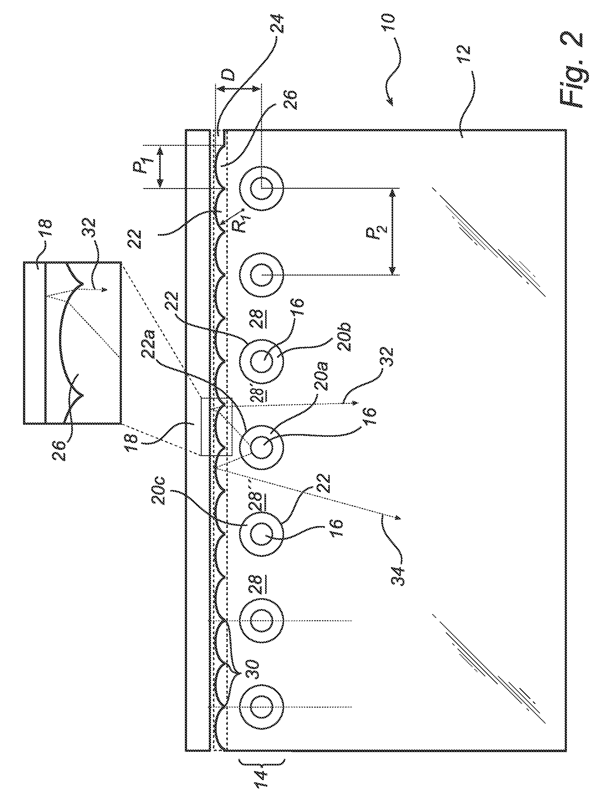
[0019]A light emitting diode (LED) based lighting device according to the present invention will now be described with reference to FIG. 2.

[0020]The lighting device denoted 10 comprises a light guide plate 12. The light guide plate 12 is transparent and can be made of glass or plastics (such as PMMA or PC), for example.

[0021]The lighting device 10 further comprises a linear array 14 of LEDs 16 arranged along a reflective edge 18 belonging to the light guide plate 12. The reflective edge 18 serves to direct any incident light back into the light guide plate 12, to avoid unintentional out-coupling of light from the light guide plate 12 via the edge. The LEDs 16 are preferably side-emitting omnidirectional LEDs.

[0022]The LEDs 16 are accommodated in cylindrical holes 20 having a circular lateral cross-section, which holes 20 are arranged in the light guide plate 12. ‘Lateral’ is in relation to the plane of the light guide plate. Each hole 20 has a circumferential side facet (cylinder wa...

second embodiment

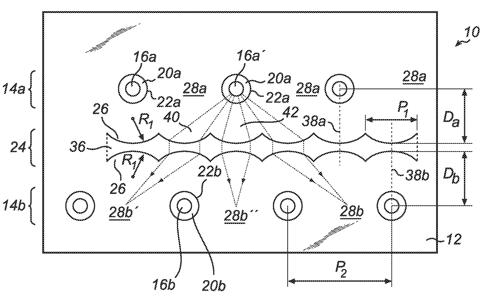
[0025]A lens array can also advantageously be used in a second embodiment, wherein two LED arrays are arranged parallel to each other, as illustrated in FIGS. 3-4. The function of the lens array is here to avoid that light from one array is absorbed or scattered at LEDs in the other array.

[0026]In a first variant (FIG. 3) of the second embodiment, the lighting device denoted 10 comprises a light guide plate 12. The light guide plate 12 should be transparent and can be made of glass or plastics (such as PMMA or PC), for example.

[0027]The lighting device 10 further comprises two parallel linear arrays 14 of LEDs 16. The LEDs 16 are preferably side-emitting omnidirectional LEDs.

[0028]The LEDs 16 are accommodated in cylindrical holes 20 having a circular lateral cross-section, which holes 20 are arranged in the light guide plate 12. Each hole 20 has a circumferential side facet (cylinder wall) 22 through which light from the accommodated LED 16 is to be coupled into the light guide plat...


PUM

PropertyMeasurementUnit
refractive indexaaaaaaaaaa
radiusaaaaaaaaaa

Abstract

The present invention relates to a lighting device (10). The device comprises a light guide plate (12), and at least one array (14) of light emitting diodes (LEDs) (16), which LEDs are accommodated in holes (20) arranged in the light guide plate. The device is characterized by an array (24) of lenses (26) arranged such that light emitted by the LEDs passing the lens array is at least partly directed towards areas (28) of the light guide plate free from holes.

Description

[0001]This application is a national stage application under 35 U.S.C. §371 of International Application No. PCT / IB2007 / 054166 filed on Oct. 12, 2007, which claims priority to European Application No. 06122321.0, filed on Oct. 16, 2006, and European Application No. 07100361.0 filed on Nov. 1, 2006, both incorporated herein by reference.FIELD OF THE INVENTION[0002]The present invention relates to lighting device comprising a light guide plate and at least one array of light emitting diodes.BACKGROUND OF THE INVENTION[0003]Progress in the brightness, lumen efficacy and affordability of solid state light sources such as light emitting diodes (LEDs) enables new lighting applications that are no longer restricted to niche markets. LEDs offer several advantages over traditional light sources, such as long lifetime, low operating voltage, instant on, etc. For these and other reasons, LEDs are becoming more and more suited for making lamps for several applications such as color variable lam...

Claims


Application Information

Patent Timeline
Patent Type & Authority Patents(United States)
IPC IPC(8): F21V7/04G02F1/1335
CPCG02B6/002G02B6/0021G02B6/0031G02B6/0068
Inventor IJZERMAN, WILLEM LUBERTUSVISSENBERG, MICHEL CORNELIS JOSEPHUS MARIEDEKKER, TIM
Owner KONINK PHILIPS ELECTRONICS NV
Why Eureka
Try Eureka