Progressive cavity compressor having check valves on the discharge endplate

a compressor and discharge end plate technology, applied in the field of compressor improvement, can solve the problems of compressor running in an inefficient off-design mode, compressor pressure mismatch between the outlet plenum and the cavity, and not included features that promote good off-design energy efficiency, so as to improve the energy efficiency of air conditioning systems and minimize leakage.

Active Publication Date: 2011-12-27
BLUE HELIX
View PDF18 Cites 8 Cited by
  • Summary
  • Abstract
  • Description
  • Claims
  • Application Information

AI Technical Summary

Benefits of technology

[0012]As shown in the accompanying drawings, an improved compressor is intended primarily for 3 to 10 ton vapor-cycle air conditioning systems. Major working section elements comprise a rotor, a stator, inlet ports, an outlet endplate, and outlet check valves. A helical-shaped rotor is driven in an eccentric orbital path inside a helical-shaped stator. In the preferred embodiment, the rotor and stator helices have varying (non-uniform) pitch in at least a portion of the working section. Rotor-stator running clearances are tight, to minimize leakage. Two or more outlet check valves regulate refrigerant discharge flow and pressure through the outlet endplate to a discharge plenum chamber. Efficient compression is provided over a wide range of compression ratios, corresponding to a wide range of ambient temperatures in an air conditioning application. The invention can improve the energy efficiency of air conditioning systems, especially at off-design conditions.
[0015]On a hot day, further compression is required beyond that provided in the working section through volume reduction of the closed cavities. This further compression to CR2 is done at the outlet end of the compressor by reduction of cavity volume against the fixed outlet endplate. The outlet check valves prevent backflow into a compressor cavity from the outlet plenum chamber, but open to allow a forward flow when there is a pressure differential between the compressor cavity and the outlet plenum chamber, that is, when the cavity pressure slightly exceeds the outlet plenum pressure. As a result, the compressor automatically adapts to a range of outside ambient temperatures, delivering the required pressure with little or no wasted compression energy.

Problems solved by technology

Both types are mass-produced at relatively low cost, but generally have not included features that promote good off-design energy efficiency.
The compressor is run in an inefficient off-design mode on days when the ambient temperature is below this maximum.
No valves are needed in a Moineau pump because the pumped fluid is incompressible.
At off-design conditions, there will be a pressure mismatch between the outlet plenum and a cavity about to be vented.
The result, in the valveless compressor, is a loss of efficiency from the sudden inflow or outflow of the working gas to or from a newly vented cavity.

Method used


Image

  • Progressive cavity compressor having check valves on the discharge endplate
  • Progressive cavity compressor having check valves on the discharge endplate
  • Progressive cavity compressor having check valves on the discharge endplate

Examples


Embodiment Construction

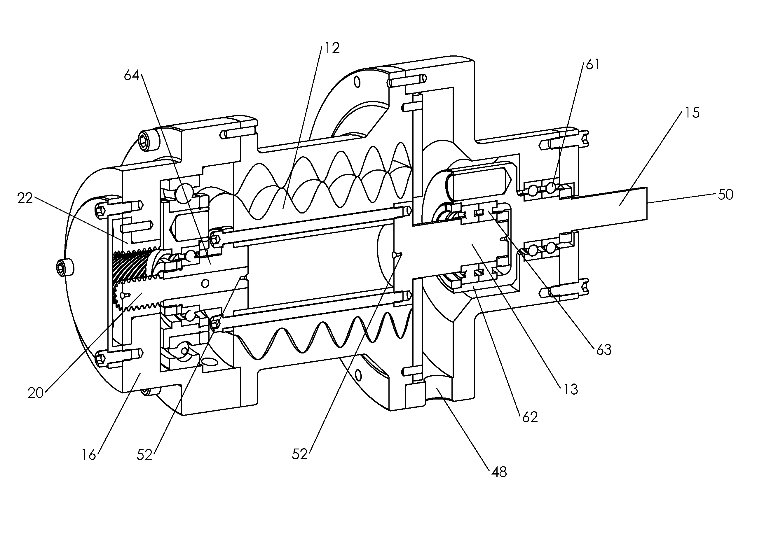
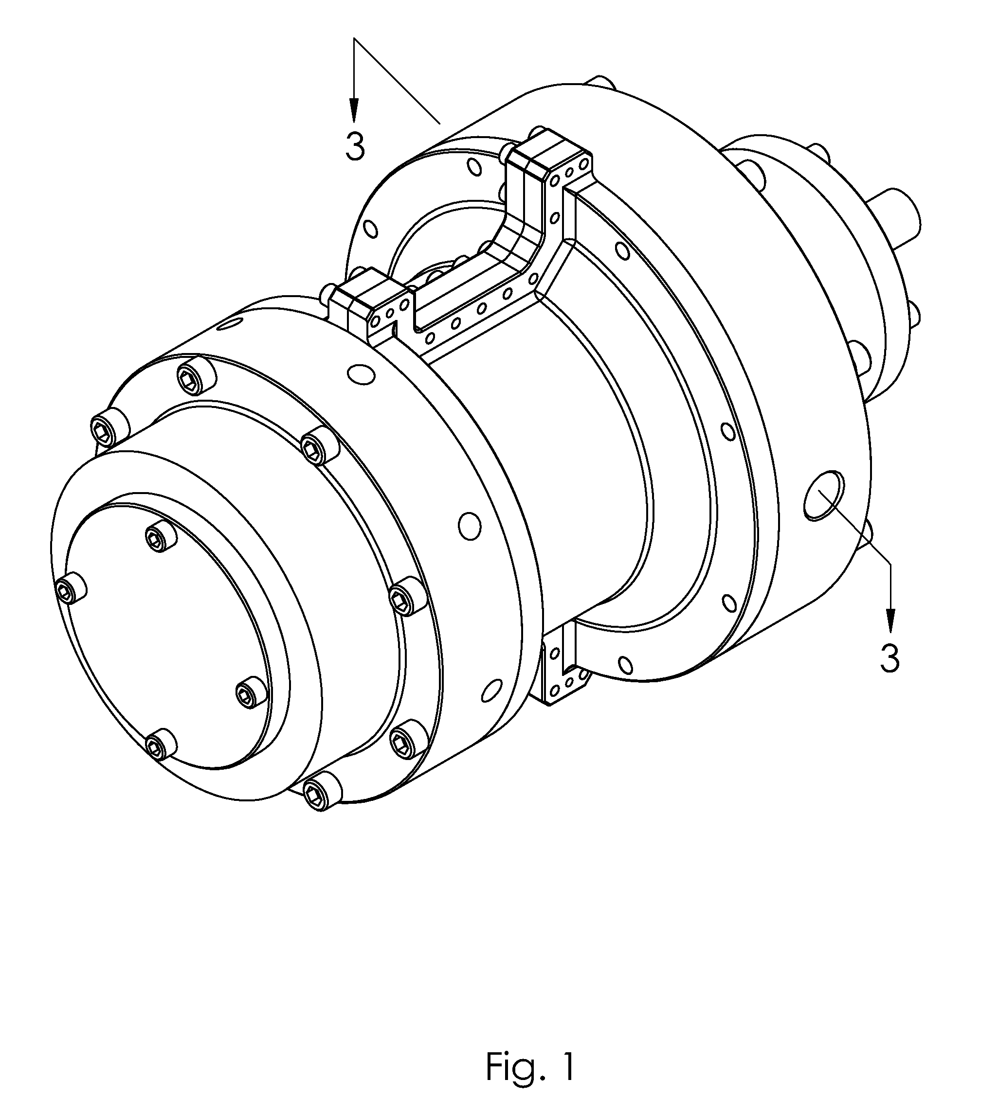
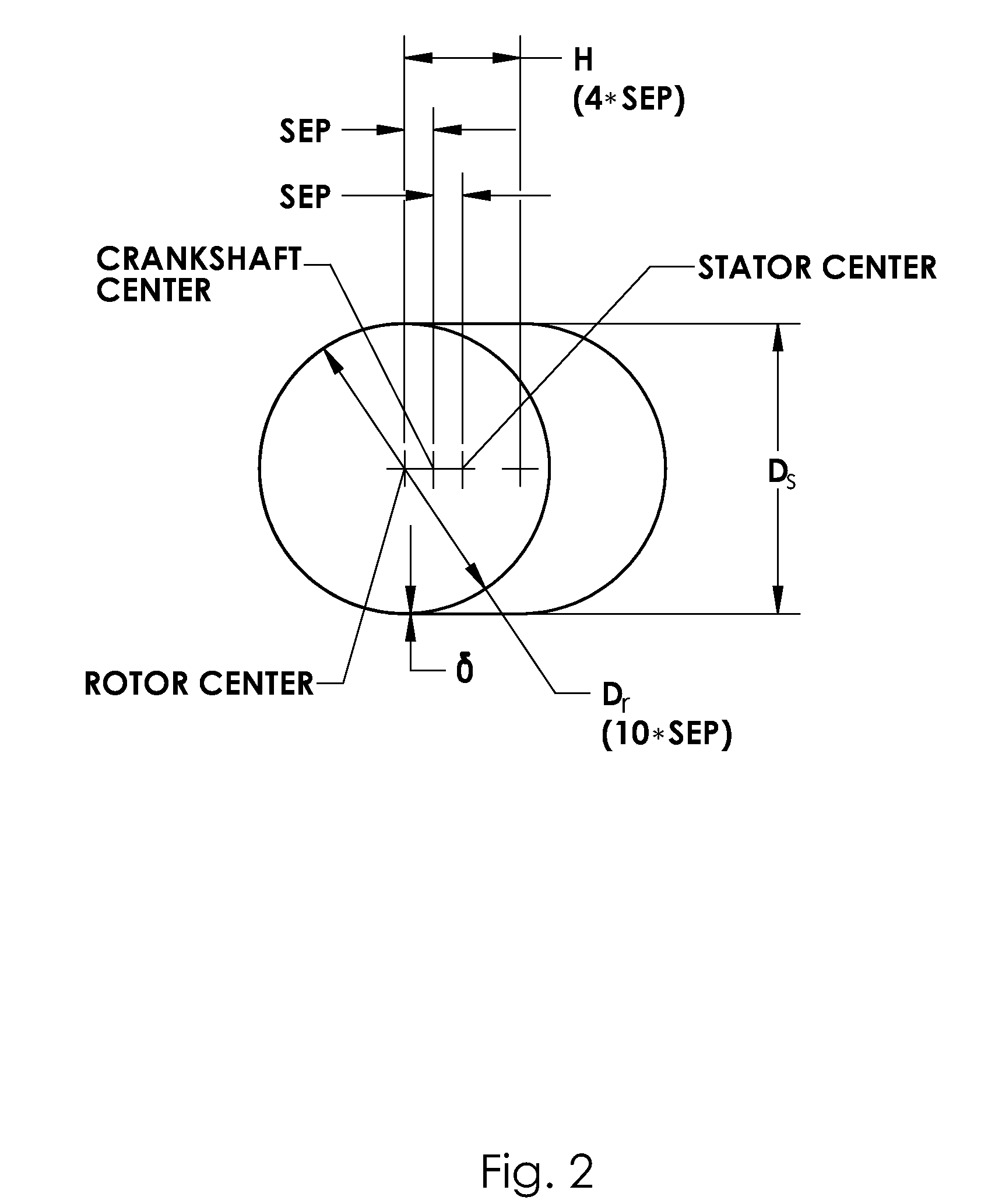
[0035]Following are the numbered parts of the varying-pitch (“preferred embodiment”) compressor, as shown in the accompanying drawings:[0036]12 rotor[0037]13 rotor shaft[0038]14 stator[0039]15 crankshaft[0040]16 inlet housing[0041]18 outlet endplate[0042]20 planetary gear[0043]22 ring gear[0044]30 inlet ports[0045]32 inlet plenum[0046]34 inlet cavity[0047]36 mid-section cavity[0048]38 outlet cavity[0049]40 outlet ports[0050]42 check valves[0051]44 endplate hole[0052]46 outlet plenum[0053]48 main outlet port[0054]50 crankshaft center[0055]52 rotor shaft center[0056]53 electric drive motor[0057]61 crankshaft bearings[0058]62 crankshaft cup[0059]63 cup bearings[0060]64 rotor extension shaft[0061]110 air conditioning condenser[0062]111 outside fan[0063]112 compressor[0064]113 room air fan[0065]114 expansion device[0066]115 evaporator[0067]116 outside unit

[0068]The preferred embodiment of the present invention, a varying-pitch progressive cavity compressor with valves, will be described ...


PUM


Abstract

A new type of progressive cavity compressor is intended primarily for 3 to 10 ton vapor-cycle air conditioning systems. Major working section elements include a rotor, a stator, inlet ports, an outlet endplate, and outlet check valves. The helical rotor is driven in an eccentric orbital path inside the helical stator. In the preferred embodiment, the rotor and stator helices have varying (non-uniform) pitch in the working section. Rotor-stator running clearances are tight, to minimize leakage. Two outlet check valves regulate refrigerant discharge flow and pressure. Efficient compression is provided over a wide range of compression ratios, corresponding to a wide range of ambient temperatures in an air conditioning application. The invention can improve the energy efficiency of air conditioning systems, especially at off-design conditions.

Description

BACKGROUND OF THE INVENTION[0001]This invention relates generally to improvements in a compressor of the type used primarily for air conditioning applications. More specifically, this invention relates to an improved compressor, preferably of the progressive cavity type, designed for improved efficiency particularly at part load operating conditions.[0002]Rene Moineau did his Ph.D. research and thesis on the progressive cavity pumping principle. (Devices employing Moineau's geometry are known, variously, as “Moineau”, “progressive cavity”, or “progressing cavity” devices). The first of his ten or more U.S. patents, U.S. Pat. No. 1,892,217, was issued in 1932. This patent mentions varying-pitch and is intended to include applicability to compressible fluids. To date, progressive cavity pumps have been used mainly to pump viscous liquids, such as petroleum, or to handle liquids containing solid material, such as drilling fluids.[0003]A few progressive cavity compressor patents have be...

Claims


Application Information

Patent Timeline
Patent Type & Authority Patents(United States)
IPC IPC(8): F01C1/10F01C5/00F03C2/00F03C4/00
CPCF04C18/1075F04C25/00F04C29/12F04C2210/1077
Inventor IRVING, JACK H.IRVING, LEGAL REPRESENTATIVE, FLORENCE L.RICHARDSON, JOHN M.RICHARDSON, LEGAL REPRESENTATIVE, BETTY J.ROBBINS, HOWARD M.
Owner BLUE HELIX
Why Eureka
Try Eureka