Thermal stimulation probe and method

a tissue and probe technology, applied in the field of tissue stimulation, can solve the problems of c-fiber activity evaluation, c-fiber activity evaluation with subsequent recording, and difficulty in selecting activation with subsequent recording, and achieve the difficulty of determining if tissue about to be damaged serves a crucial brain function,

Active Publication Date: 2011-12-27
MEDOC
View PDF10 Cites 44 Cited by
  • Summary
  • Abstract
  • Description
  • Claims
  • Application Information

AI Technical Summary

Benefits of technology

[0010]An aspect of some embodiments of the invention relates to a physiological temperature stimulation probe structure including a primed heat-sink or source in close thermal contact with a temperature stimulation element such that the readied heat sink / source can rapidly change the temperature of the temperature stimulation element. In an exemplary embodiment of the invention, the temperature stimulation element is actively controlled and optionally continuously controlled to offset the effect of the sink / source when not desired. Alternatively or additionally, one or more temperature sensors are used to provide closed loop control of the stimulation element temperature. In an exemplary embodiment of the invention, the heat sink / source has a low enough thermal impedance so that it can quickly change the temperature of the temperature stimulation element and also a high enough thermal capacity to provide such an effect.
[0018](b) a thermal sink / source with a relatively high effective thermal capacity and a relatively low thermal impedance, such that said thermal sink / source sink can rapidly change a temperature of said heat control element, at a rate above 10 degrees Celsius per second, from a temperature of below 100 degrees Celsius; and

Problems solved by technology

However, selective activating with subsequent recording for the evaluation of C-fibers activity is apparently more difficult.
These methods, however, have not found widespread clinical use, possibly due to their complexity and / or poor sensation generation quality.
During brain surgery there is a general difficulty of determining if tissue about to be damaged serves a crucial brain function.
Due to the difficult in determining if the correct effect has been achieved, there exists a problem of patients which are immobilized but are conscious and / or feel pain during surgery.
Even if not conscious, pain can cause an increase in sensed or even chronic pain after surgery,

Method used


Image

  • Thermal stimulation probe and method
  • Thermal stimulation probe and method
  • Thermal stimulation probe and method

Examples


Embodiment Construction

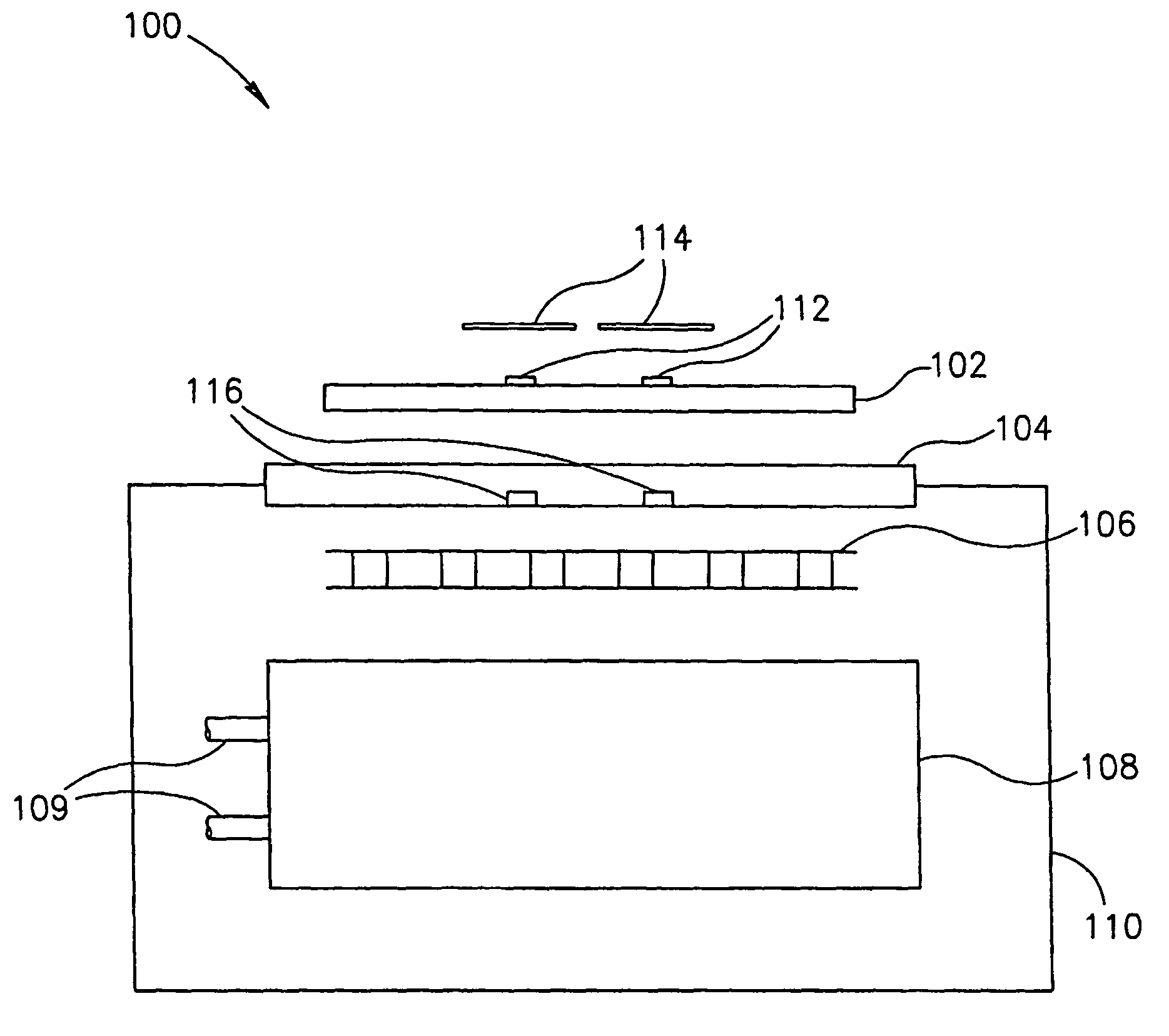
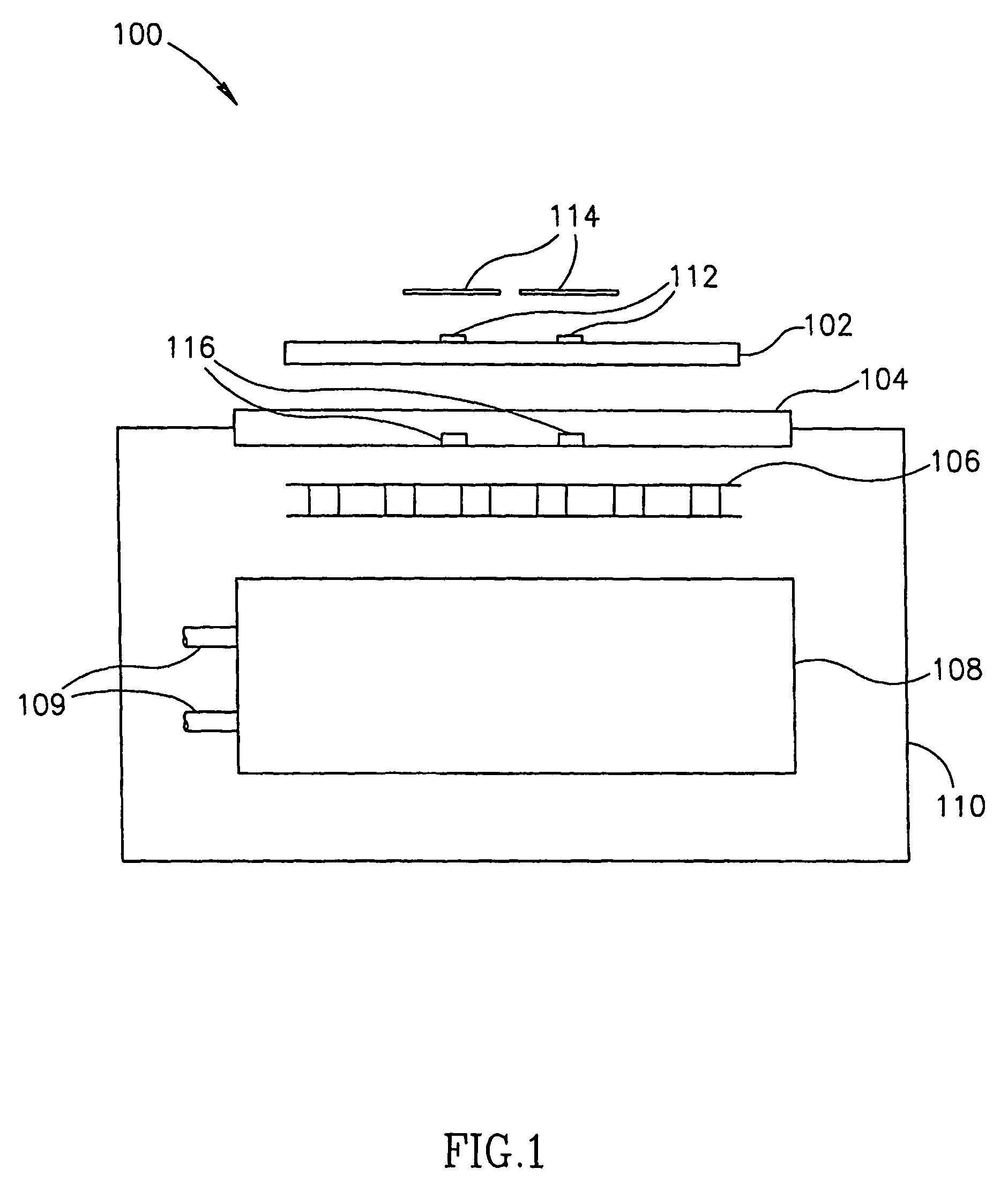
[0066]FIG. 1 is a schematic side illustration of physiological temperature stimulation probe 100 in accordance with an exemplary embodiment of the invention. The probe comprises a contact a heating element, which is in contact with the tissue to be stimulated. In an exemplary embodiment of the invention, the heating element is a resistive foil 102, for example, a foil of Nickel-Iron optionally covered by 25 or 50 microns of Kapton on all sides (or only in contact with the skin) and having an area of 24×24 mm. Optionally, the foil heater is controllable as a linear or two dimensional array of heating elements. In an exemplary embodiment of the invention, this heating foil is used to provide a rapid onset of heating stimulation. Optionally, one or more temperature sensors 112 are provided between the foil and the tissue, optionally shielded from the tissue, for example by a thin layer of Kapton 114. These sensors are optionally used to detect and act as sensors for control of the temp...


PUM


Abstract

A physiological thermal stimulation probe, comprising: (a) an electrically controlled heat control element with a relatively low thermal capacity and adapted for contact with tissue on one side thereof; (b) a thermal sink / source with a relatively high effective thermal capacity and a relatively low thermal impedance, such that said thermal sink / source sink can rapidly change a temperature of said heat control element, at a rate above 10 degrees Celsius per second, from a temperature of below 100 degrees Celsius; and (c) circuitry which activates said heat control element to achieve a desired temperature stimulation profile of said tissue.

Description

RELATED APPLICATIONS[0001]The present application is a US National Phase of PCT Application No. PCT / IL2004 / 000435, filed on May 20, 2004, published as WO 2004 / 103230. The present application also claims the benefit under 119(e) of U.S. provisional patent application No. 60 / 472,480, the disclosure of which is incorporated herein by reference.FIELD OF THE INVENTION[0002]The present invention is related to thermal stimulation of tissue.BACKGROUND OF TH INVENTION[0003]The pain mediating system in a human consists of two kinds afferent fibers: A-delta and C-fibers. These afferent pain fibers characterized by different physiological parameters, for example, conduction velocity (15-50 ml / s for A-delta fibers and <2 m / s for C-fibers). These two fiber types project to different parts of the dorsal horn of the spinal cord. In addition, stimulation of each kind of nociceptors evokes different type of sensation: A-delta fibers mediate first (sharp, pin-prick) pain sensation; C-fibers mediate...

Claims


Application Information

Patent Timeline
Patent Type & Authority Patents(United States)
IPC IPC(8): A61F7/00A61B5/0484A61F7/02
CPCA61B5/0484A61B5/4821A61F7/007A61F2007/0001A61F2007/0071A61F2007/0075A61F2007/0076A61B5/377
Inventor GAFNI, EHUDGRANOVSKY, YELENA
Owner MEDOC
Why Eureka
Try Eureka