Pulsed voltage electrospray ion source and method for preventing analyte electrolysis

a technology of electrospray ion source and pulsed voltage, which is applied in the direction of particle separator tube details, separation processes, instruments, etc., can solve problems such as unwanted effects

Inactive Publication Date: 2011-12-27
UT BATTELLE LLC
View PDF32 Cites 33 Cited by
  • Summary
  • Abstract
  • Description
  • Claims
  • Application Information

AI Technical Summary

Problems solved by technology

In general, problems with ESI source analyte electrolysis arise where the analyte has a low oxidation potential or high reduction potential relative to the surface potential generated at the electrode surface in order to produce the current required for ionization.
Unfortunately, both methods introduce products of the buffering reaction to the solution that may have unwanted effects.

Method used


Image

  • Pulsed voltage electrospray ion source and method for preventing analyte electrolysis
  • Pulsed voltage electrospray ion source and method for preventing analyte electrolysis
  • Pulsed voltage electrospray ion source and method for preventing analyte electrolysis

Examples


examples

[0053]It should be understood that the Examples described below are provided for illustrative purposes only and do not in any way limit the scope of the invention.

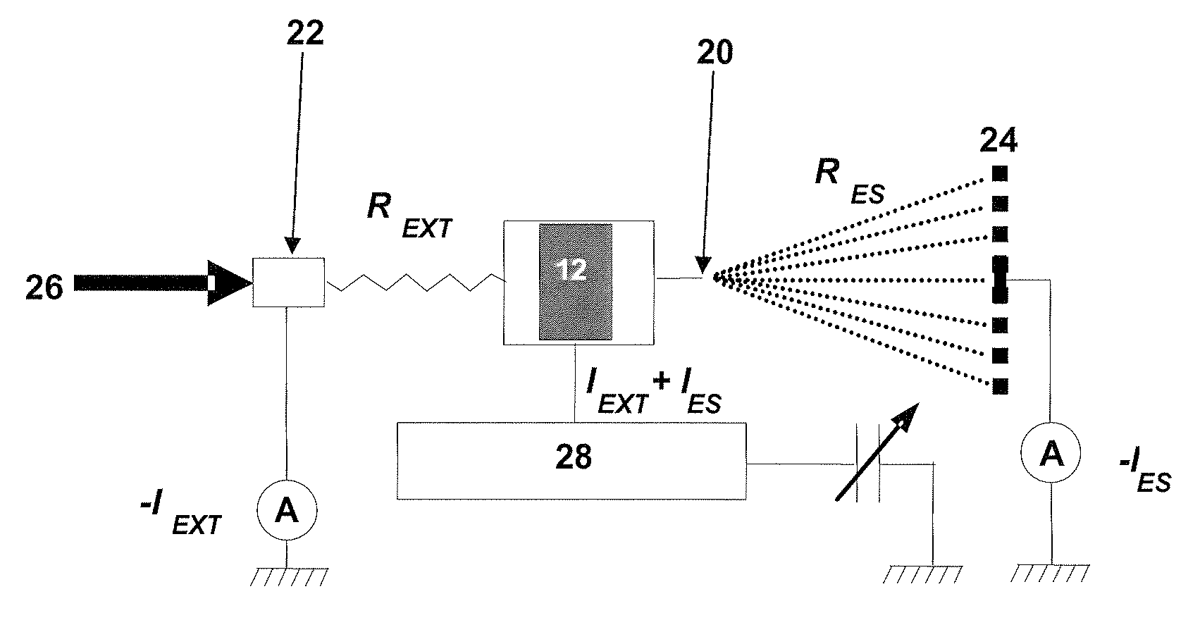
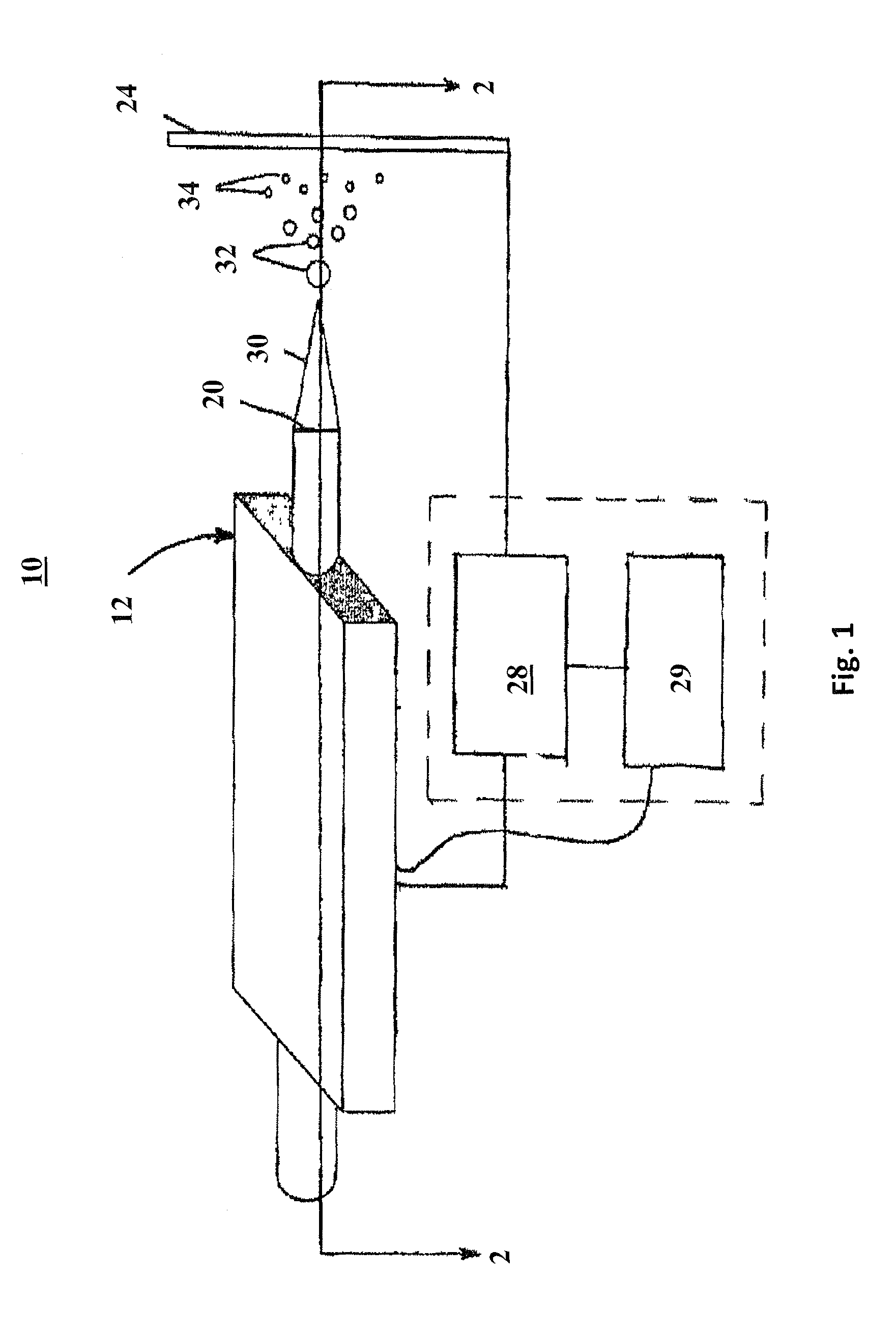
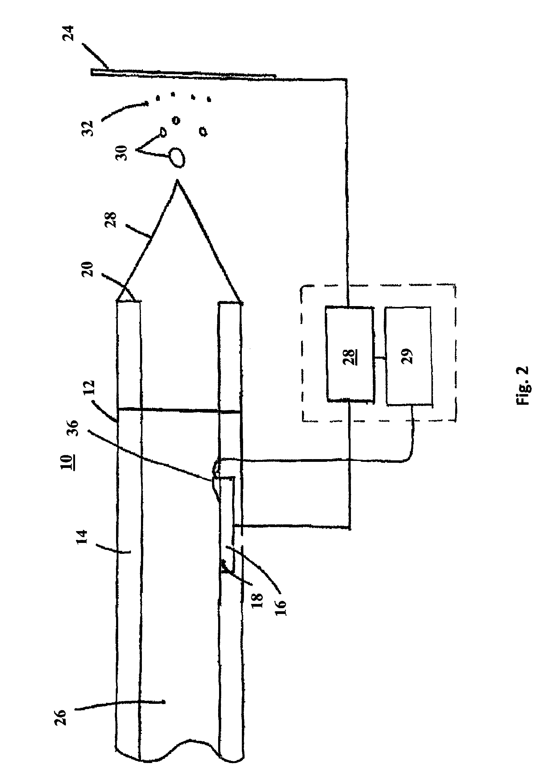
[0054]In order to evaluate the pulsed voltage concept, a pulsed electrospray ionization system was built and tested. The power system was composed of a transistor-transistor logic (TTL) pulse generator, a high voltage (HV) power supply and ground that were coupled to a high voltage pulse generator (PVX-4140, Directed Energy, Fort Collins, Colo.). Although these components were separate, it is envisioned that the components could be packaged into a single component. The output of the high voltage pulse generator was used to supply pulse waves to a porous flow through carbon electrode of the electrospray emitter.

[0055]Mass spectra of reserpine, an oxidation sensitive compound, were then acquired under standard DC conditions and using a variety of different pulse waves. FIG. 5 shows the structure of reserpine and the proposed...


PUM


Abstract

An electrospray ion source and method of operation includes the application of pulsed voltage to prevent electrolysis of analytes with a low electrochemical potential. The electrospray ion source can include an emitter, a counter electrode, and a power supply. The emitter can include a liquid conduit, a primary working electrode having a liquid contacting surface, and a spray tip, where the liquid conduit and the working electrode are in liquid communication. The counter electrode can be proximate to, but separated from, the spray tip. The power system can supply voltage to the working electrode in the form of a pulse wave, where the pulse wave oscillates between at least an energized voltage and a relaxation voltage. The relaxation duration of the relaxation voltage can range from 1 millisecond to 35 milliseconds. The pulse duration of the energized voltage can be less than 1 millisecond and the frequency of the pulse wave can range from 30 to 800 Hz.

Description

CROSS REFERENCE TO RELATED APPLICATIONS[0001]This application is a continuation-in-part of U.S. patent application Ser. No. 12 / 237,892, entitled “Electrospray Ion Source with Reduced Analyte Electrolysis,” filed Sep. 25, 2008, the entirety of which is incorporated herein by reference.STATEMENT REGARDING FEDERALLY SPONSORED RESEARCH OR DEVELOPMENT[0002]This invention was made with government support under contract no. DE-AC05-00OR22725 awarded by the U.S. Department of Energy. The Government has certain rights in the invention.FIELD OF THE INVENTION[0003]The present invention relates to an electrospray ionization source and methods of using the same.BACKGROUND OF THE INVENTION[0004]Electrospray ionization (ESI) sources are used to produce gas phase analyte ions for analysis by analytical instruments, such as mass spectrometers. Under common electrospray ionization mass spectrometry (ESI-MS) conditions most analytes are not directly affected by the electrochemical process occurring wh...

Claims


Application Information

Patent Timeline
Patent Type & Authority Patents(United States)
IPC IPC(8): B05B5/03H01J49/00
CPCH01J49/022H01J49/165
Inventor KERTESZ, VILMOSVAN BERKEL, GARY
Owner UT BATTELLE LLC
Why Eureka
Try Eureka