
Transceiver

a transceiver and receiver technology, applied in the field of transceivers, can solve the problems of carrier leakage, difficult filter realization, and large physical size of the off-chip, and achieve the effect of reducing interference and reducing interferen

Active Publication Date: 2011-12-27
RENESAS ELECTRONICS CORP
View PDF5 Cites 7 Cited by
  • Summary
  • Abstract
  • Description
  • Claims
  • Application Information

AI Technical Summary

Benefits of technology

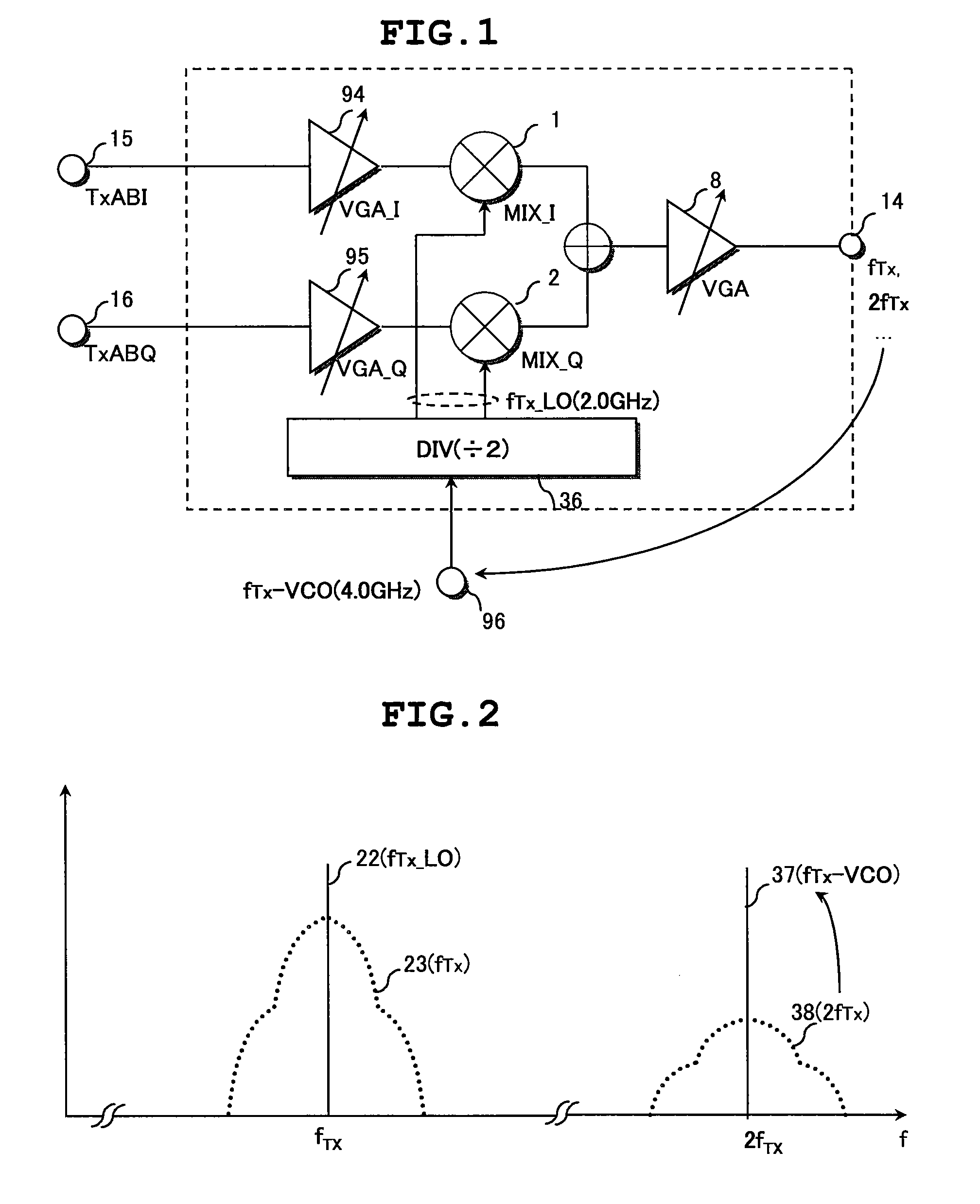
The patent text discusses a problem in a communication RF IC called a DUC architecture-based transmitter. The text describes how the interference between the transmitter's local signals and the carrier signal leakage can cause an injection lock phenomenon, which negatively affects the accuracy of the transmitter's phase. The text explores various solutions to this problem, such as eliminating the transmitter-side voltage-controlled oscillator or using a band-pass filter. However, each solution has its limitations, and the inventors found that none of these solutions fully addressed the problem. The patent proposes a new solution to reduce interference and improve the accuracy of the transmitter's phase.

Problems solved by technology

The solution of using a filter for the purpose of attenuating a high-level sideband would be very simple and work well with a low electric power, however such filter is hard to realize and needs a physically large off-chip size.
Also, in this document, it is reported that carrier leakage is a serious drawback of DUC architecture.

Method used


Image

  • Transceiver
  • Transceiver
  • Transceiver

Examples


Embodiment Construction

1. Summary of the Preferred Embodiments

[0059]First, the preferred embodiments of the invention herein disclosed will be presented in outline. In the description here, the reference numerals, characters or signs to refer to the drawings, which are accompanied with paired round brackets, only exemplify what the concepts of components referred to by the numerals, characters or signs contain.

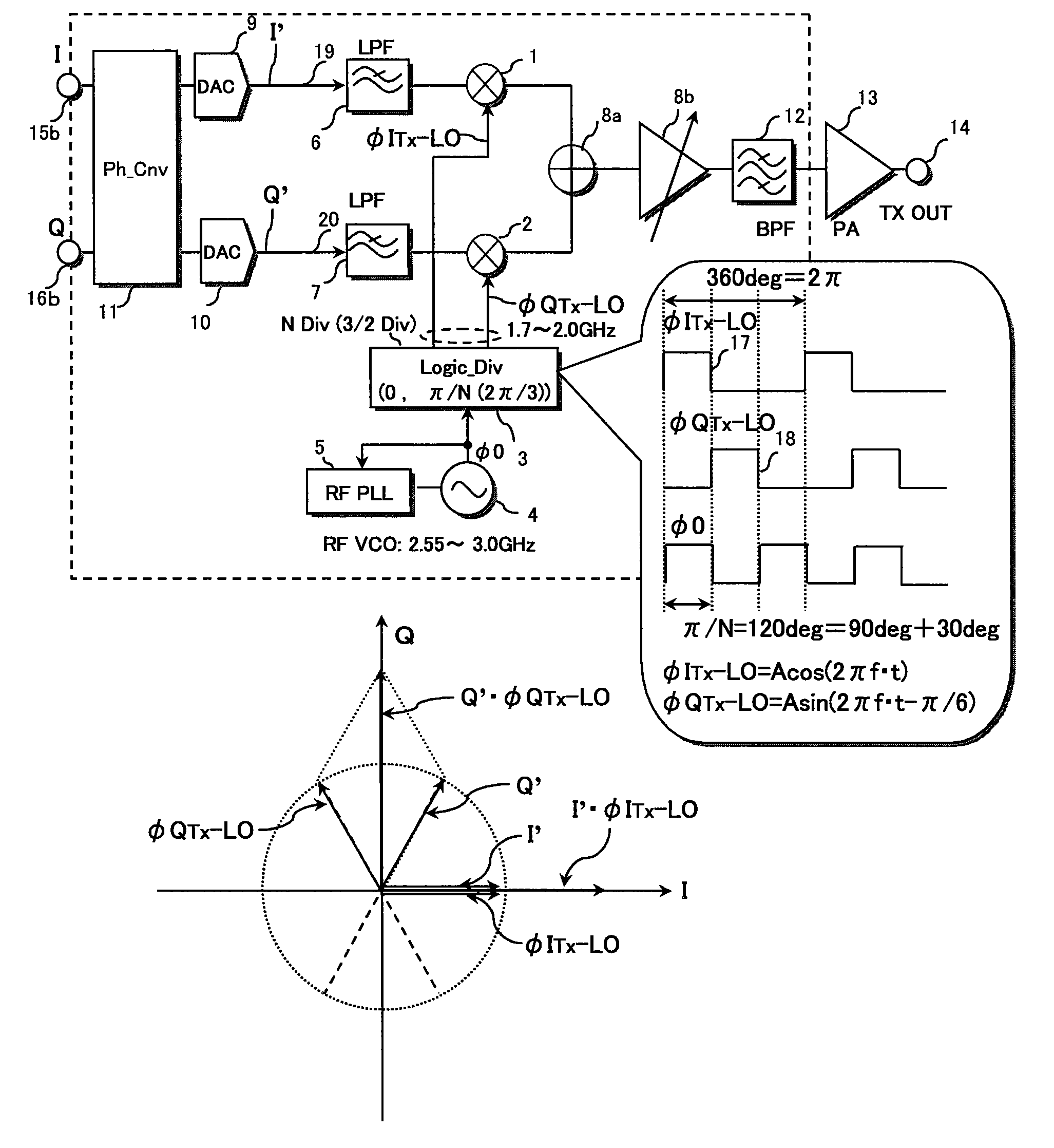
[0060][1] A transceiver according to a preferred embodiment of the invention has a receiver including a receiver-side demodulator for converting a received RF receive signal into an analog receive signal, and a transmitter including a transmitter-side modulator for converting an analog transmit signal into an RF transmit signal.

[0061]The transmitter further includes a digital-to-analog converter (9,10) for converting a digital transmit signal (I, Q) into the analog transmit signal (I′, Q′). The transmitter further includes: a transmitter-side voltage-controlled oscillator (4); and a transmitter-side...


PUM


Abstract

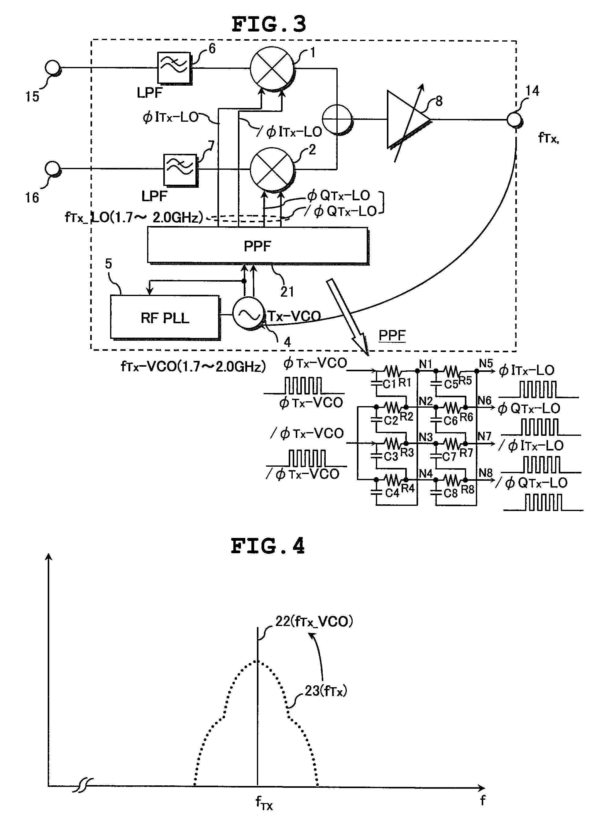
The transmitter of the transceiver includes: a transmitter-side mixers of a transmitter-side modulator; a transmitter-side voltage-controlled oscillator; and a transmitter-side divider. The divider having a dividing factor of a non-integral number is supplied with an oscillating output of the oscillator. A pair of non-quadrature local signals having a phase difference of 90° plus a predetermined offset angle is produced by the divider and supplied to the mixers. The transmitter includes a phase-shift unit which converts a pair of quadrature transmit signals having a phase difference of about 90° on an analog basis into a pair of non-quadrature shifted transmit signals. Consequently, quadrature modulation is performed by the mixers. Use of a similar configuration enables the reduction in interference of an RF signal with local signals supplied to receiver-side mixers of the receiver.

Description

CLAIM OF PRIORITY[0001]The Present application claims priority from Japanese application JP 2007-158610 filed on Jun. 15, 2007, the content of which is hereby incorporated by reference into this application.FIELD OF THE INVENTION[0002]The present invention relates to a transceiver which has a receiver and a transmitter, and is used in RF communications by mobile phones, wireless LANs and the like. Particularly, it relates to a useful technique useful for reducing the interference on local signals supplied to a transmitter-side modulator or a receiver-side demodulator by RF signals.BACKGROUND OF THE INVENTION[0003]The ubiquitous coverage, which is an ability of communication terminal devices such as mobile phone terminals communicating by wireless anywhere in the world has not been actualized today, but has been under development.[0004]Their mobile systems include GSM, GPRS, EDGE, WCDMA, DCS and PCS cellular systems. The systems have the feature of signals according to a constant env...

Claims


Application Information

Patent Timeline
Patent Type & Authority Patents(United States)
IPC IPC(8): H04B1/38H04B1/04H04B1/30H04B1/3822H04B1/40
CPCH04B1/28
Inventor TANAKA, SATOSHIKAMIZUMA, HIROSHIMAEDA, KOJICHA, SUNGWOOAKAMINE, YUKINORIYAMAWAKI, TAIZO
Owner RENESAS ELECTRONICS CORP
Learn More