Phase modulation device for an ophthalmic instrument, ophthalmic instruments equipped with such device, and related calibration method

a phase modulation and ophthalmic instrument technology, applied in the field of phase modulation devices for ophthalmic instruments, can solve the problems of degrading the quality of optical instruments, losing resolution, and degrading the quality of focusing lasers on the retina, so as to reduce the discomfort of patients, improve the enslavement process, and effective control of phase modulation devices

Active Publication Date: 2012-01-03
IMAGINE EYES
View PDF5 Cites 9 Cited by
  • Summary
  • Abstract
  • Description
  • Claims
  • Application Information

AI Technical Summary

Benefits of technology

[0020]A phase modulation device is thus provided that makes it possible to carry out periodic calibrations of the ophthalmic instruments, without the need to illuminate the patient's eye or to use an artificial eye.
[0024]The phase modulation device according to the invention can advantageously comprise means for modifying the control applied to the modulation means, so as to reduce a discrepancy between the modulation instruction and the modulation carried out on the secondary beam.
[0039]It could have seemed obvious, in order to limit the visual discomfort of a patient while ensuring effective control of a phase modulation device, to improve the enslavement process described in the document FR2 866 551 by using for the measurement of eye aberrations, a source of illumination that is invisible to the eye, typically at an infrared wavelength greater than 900 nanometers. However, due to the eye's chromatism, enslavement of the modulation means carried out in the infrared would not necessarily have been valid for the main beam if the latter had a different wavelength, typically in the visible spectrum. Moreover, use of a secondary beam interacting with the eye necessarily limits the flux available for the measurement due to eye safety standards. This suggests that this measurement is carried out with a low recurrence rate or with a phase analyzer having a reduced number of measurement points. In both cases, the quality of the enslavement is reduced.
[0040]The invention provides an ingenious way of enslaving the modulation means, because in the preferred case where a wavelength of the secondary beam is approximately equal to a wavelength of the main beam, it makes it possible to avoid both achromatism problems of the eye and of the set of optical elements used, including the phase modulation means, in particular in the case where the modulation means comprise a liquid-crystal phase modulator.

Problems solved by technology

In all cases, aberrations of the different optical elements of the eye cause aberrations of the wave front of the main beam, which degrades the quality of the optical instrument.
Thus, in the case of retinal imaging, the image loses resolution and, in the case of the optical treatment of the eye, the quality of focusing the laser on the retina is degraded.
In the case of a visual simulation appliance operating in a closed loop, the problem generally faced is the need to direct light into the patient's eye, resulting in dazzling and thus disturbance to the simulation process, as well as creating a sensation of ocular discomfort.
In this case, no light is directed into the patient's eye, and consequently, no wave front measurement is possible since no light returns from the eye.
Such an approach has the drawback of imperfection of the modulation means (linearity problem, hysteresis, temperature drift).
The errors generated on the modulation by these defects are not compensated for by a feedback loop (closed loop) and thus degrade the results of the correction or simulation.
Moreover, a further problem resides in the need to provide a learning or calibration stage of the adaptive optics process, the periodicity of which typically depends on the precision and stability requirements of a given application.
The problem also arises of overcoming aberrations of the optical system itself.
A single measurement of the system aberrations carried out during its set-up is generally insufficient to ensure that these aberrations are known over a long period (typically several months) due to their temperature-dependence.

Method used


Image

  • Phase modulation device for an ophthalmic instrument, ophthalmic instruments equipped with such device, and related calibration method
  • Phase modulation device for an ophthalmic instrument, ophthalmic instruments equipped with such device, and related calibration method
  • Phase modulation device for an ophthalmic instrument, ophthalmic instruments equipped with such device, and related calibration method

Examples


first embodiment

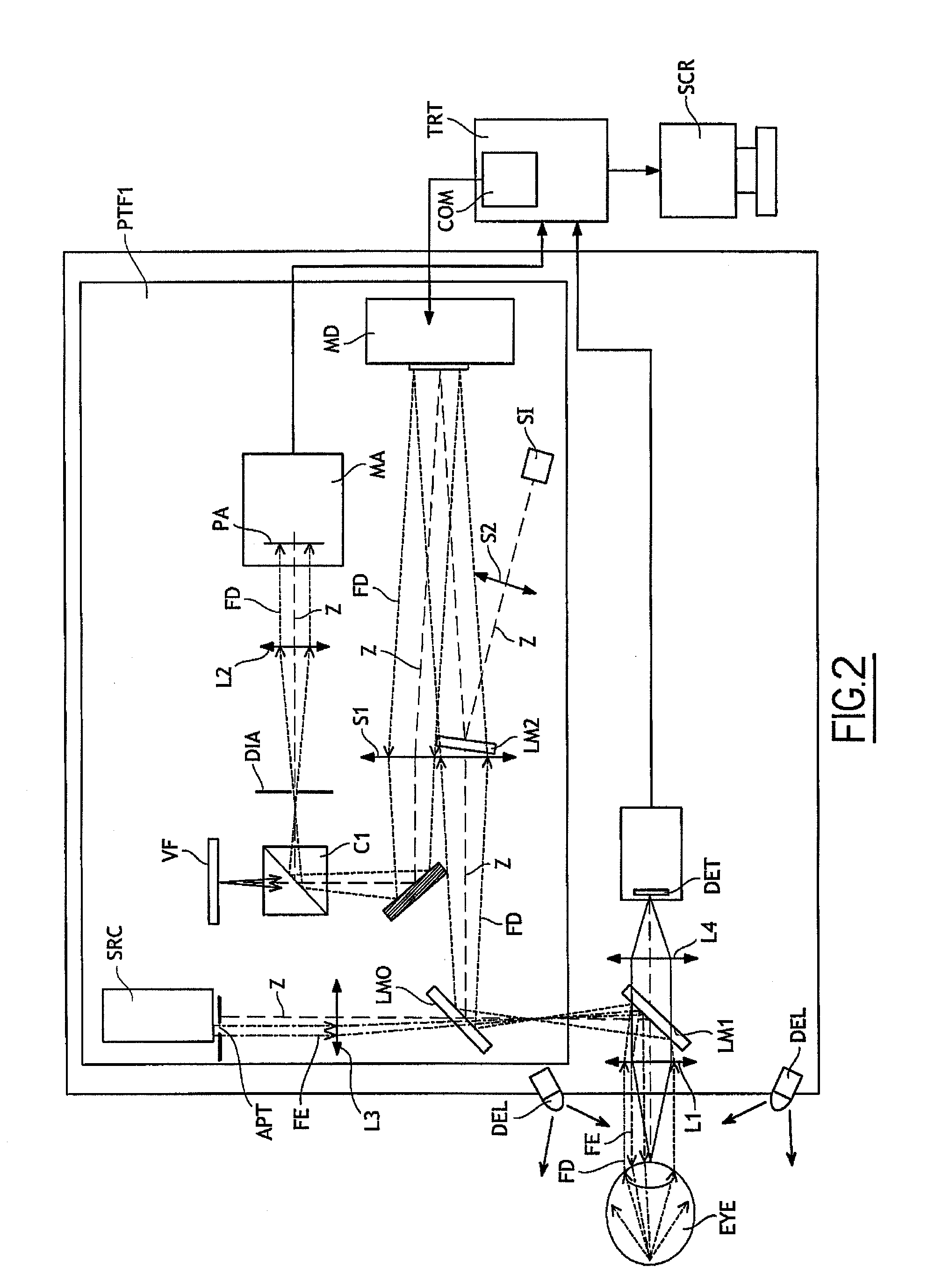
[0086]the process according to the invention thus makes it possible to calibrate the device according to the invention, without using an artificial eye, and in the absence of the main beam FA.

second embodiment

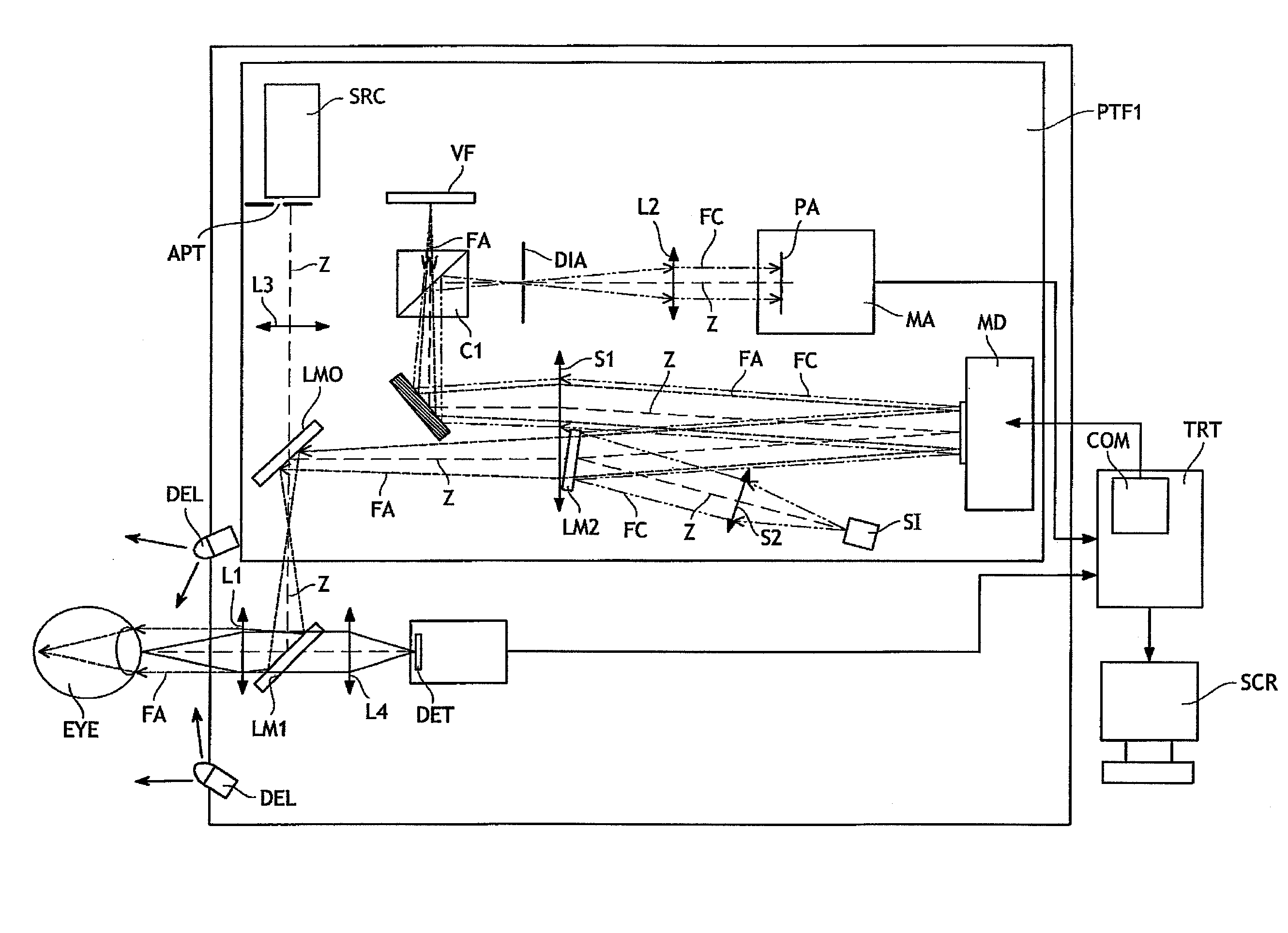
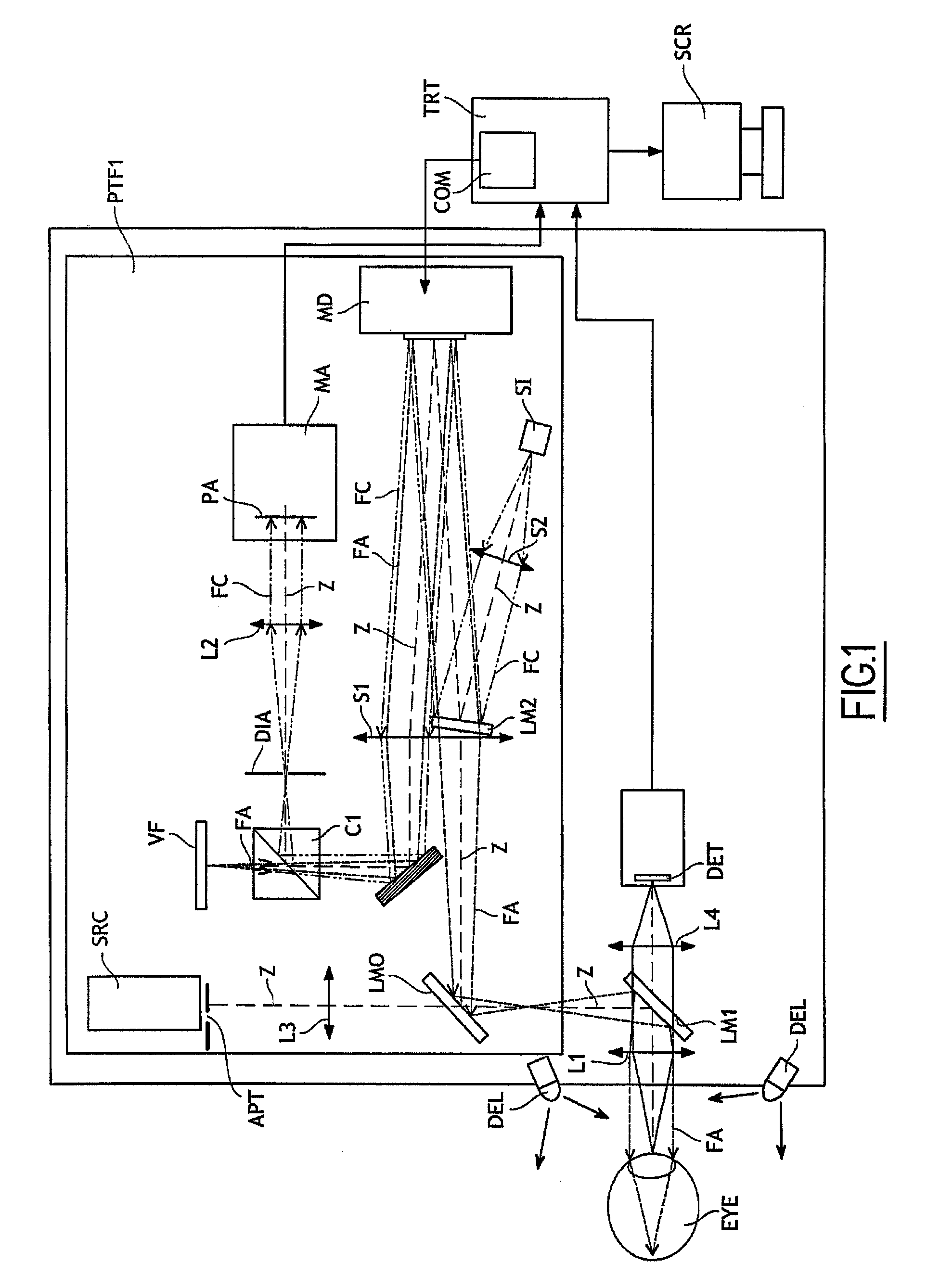
[0087]the process according to the invention, implemented in the simulator according to the invention and shown in FIG. 1, comprises the following steps:[0088]controlling the modulation means according to the modulation instruction,[0089]positioning an eye to be examined at the output of the simulator according to the invention,[0090]emitting the measurement light beam FC,[0091]emitting the main light beam FA,[0092]modulating the phase of the wave front of the secondary beam, according to the modulation instruction, by the modulation means MD,[0093]modulating the phase of the wave front of the main light beam FA interacting with the eye, according to a modulation instruction, the modulations of the main and measurement beams being simultaneous,[0094]measuring the phase modulation carried out by the modulation means on the secondary beam, and[0095]if the phase modulation carried out by the modulation means on the secondary beam is approximately equal to the modulation instruction, ma...


PUM

PropertyMeasurementUnit
infrared wavelengthaaaaaaaaaa
wavelengthaaaaaaaaaa

Abstract

A phase modulation device implemented in an ophthalmic instrument using a main light beam interacting with an eye, the device including: an apparatus for modulating the phase of the wave front of the main light beam, a controller for controlling the phase modulation apparatus following a modulation instruction, and an analyzer for analyzing the thus-performed modulation of the phase of the wave front of the main light beam, further including emitting a secondary light beam, an apparatus for directing the secondary light beam along an optical path to the modulation apparatus, then to the analyzer, and in that the optical path does not pass through the eye, and in that the controller and the analyzer receiving the modulated secondary light beam cooperate, during a stage called a learning stage, to supply data regarding the response of the phase modulation apparatus to a set of predetermined modulation instructions.

Description

[0001]This application is a U.S. National Stage under 35 U.S.C. §371 of International Application No. PCT / FR2008 / 050285, filed Feb. 20, 2008, which claims priority from French Patent Application No. 0701249, filed Feb. 21, 2007.BACKGROUND[0002]The present invention relates to a phase modulation device for an ophthalmic instrument using a light beam interacting with an eye. It also relates to ophthalmic instruments implementing such a device, as well as to a calibration process for these ophthalmic instruments.[0003]The field of the invention is more particularly that of visual correction simulators and ophthalmic imaging devices, in particular for high-resolution retinal imaging.[0004]Ophthalmic instruments, such as for example instruments for retinal imaging or for optical laser treatment on the retina, operate with a main beam intended to pass through the various optical elements (cornea, crystalline lens, etc.) of a patient's eye, either by a beam incident on the eye (case of opt...

Claims


Application Information

Patent Timeline
Patent Type & Authority Patents(United States)
IPC IPC(8): A61B3/10A61B3/00G02F1/01
CPCA61B3/1015
Inventor LEVECQ, XAVIER
Owner IMAGINE EYES
Why Eureka
Try Eureka