Hydrogen and carbon utilization in synthetic fuels production plants

a technology of synthetic fuels and hydrogen and carbon, which is applied in the direction of combustible gas production, combustible gas purification/modification, chemical production, etc., can solve the problems of conventionally inefficient utilization of “lean” hydrogen streams as fuel for production plants, and achieve the effect of effective utilization of hydrogen and carbon and efficient utilization of various hydrogen and carbon streams

Inactive Publication Date: 2012-01-03
RES USA LLC
View PDF12 Cites 3 Cited by
  • Summary
  • Abstract
  • Description
  • Claims
  • Application Information

AI Technical Summary

Benefits of technology

[0017]The foregoing has outlined rather broadly the features and technical advantages of the invention in order that the detailed description of the invention that follows may be better understood. Additional features and advantages of the invention will be described hereinafter that form the subject of the claims of the invention. It should be appreciated by those skilled in the art that the conception and the specific embodiments disclosed may be readily utilized as a basis for modifying or designing other structures for carrying out the same purposes of the invention. It should also be realized by those skilled in the art that such equivalent constructions do not depart from the spirit and scope of the invention as set forth in the appended claims.

Problems solved by technology

These “lean” hydrogen streams are conventionally inefficiently utilized as fuel for the production plant.

Method used


Image

  • Hydrogen and carbon utilization in synthetic fuels production plants
  • Hydrogen and carbon utilization in synthetic fuels production plants
  • Hydrogen and carbon utilization in synthetic fuels production plants

Examples


embodiment 300

[0051]FIG. 3A is a block diagram depicting utilization, according to an embodiment 300 of this invention, of hydrogen-rich gas stream(s) in line(s) 8 and hydrogen-lean gas stream(s) in line(s) 9 produced in hydrogen extraction unit(s) 7 of a synthetic fuels production plant. According to this disclosure, rather than being sent to fuel system 29, line(s) 9 carrying hydrogen-lean gas fluidly connect hydrogen extraction unit(s) 7 with one or more hydrocarbon synthesis reactor or catalyst activation reactor (for fresh catalyst activation and / or spent catalyst re-activation), as indicated by box 30. Thus, box 30 represents one or more hydrocarbon synthesis reactor 11 or a catalyst activation (or re-activation) reactor 17 as depicted in FIG. 4 and further described hereinbelow.

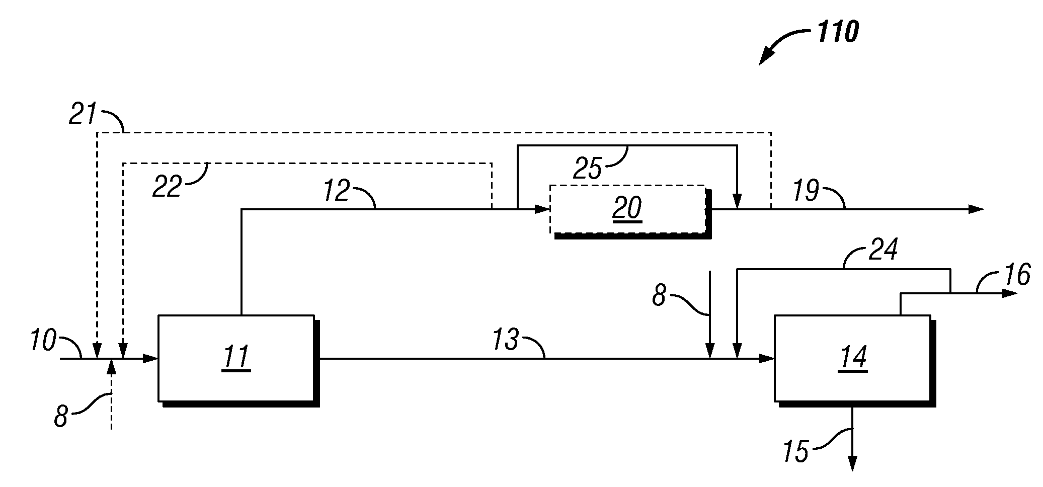
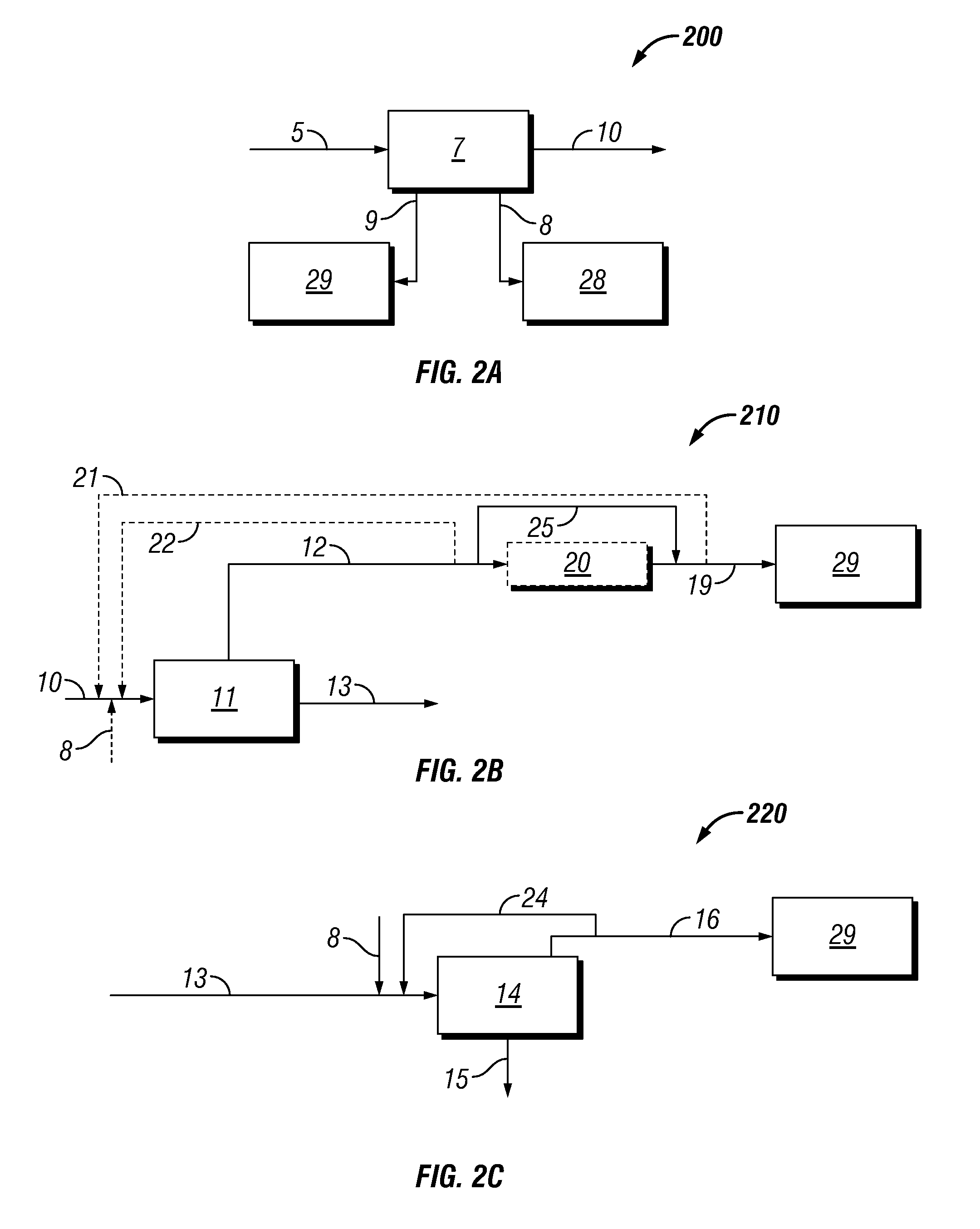
[0052]FIG. 2B is a block flow diagram depicting conventional utilization 210 of first gas byproduct stream(s) 19 separated from gas products 12 exiting a hydrocarbon synthesis reactor(s) 11 of a synthetic fuels prod...

embodiment 310

[0053]FIG. 3B is a block flow diagram depicting utilization, according to an embodiment 310 of this invention, of synthesis gas in first gas byproduct separated via line(s) 19 from gas products 12 exiting a hydrocarbon synthesis reactor(s) 11 of a synthetic fuels production plant. According to this disclosure, at least a portion of first gas byproduct in line(s) 19 is introduced into one or more hydrocarbon synthesis reactors or catalyst activation reactors as indicated by box 30. Thus, reactor 30 may be one or more hydrocarbon synthesis reactor 11 or one or more catalyst activation or re-activation reactor 17 as depicted in FIG. 4 and further described hereinbelow.

[0054]FIG. 2C is a block flow diagram depicting conventional utilization 220 of hydrogen-rich second gas byproduct in line(s) 16 separated from hydrocarbon liquid products 15 in product upgrading unit(s) 14 of a synthetic fuels production plant. As indicated in FIG. 2C, line(s) 16 conventionally serve to introduce hydroge...

embodiment 320

[0055]FIG. 3C is a block flow diagram depicting utilization, according to an embodiment 320 of this invention, of hydrogen-rich second gas in line(s) 16 separated from hydrocarbon liquid products in line(s) 15 via product upgrading unit(s) 14 of a synthetic fuels production plant. According to this embodiment, line(s) 16 is fluidly connected with one or more hydrocarbon synthesis reactors or catalyst activation reactors as indicated by box 30, whereby at least a portion of second gas byproduct in line(s) 16 may be introduced into one or more hydrocarbon synthesis reactors or catalyst activation reactors 30. Thus, at least a portion of second gas byproduct in line(s) 16 may be introduced into a hydrocarbon synthesis reactor 11 or a catalyst activation or re-activation reactor 17 as depicted in FIG. 4 and further described hereinbelow.

Method of Using H2-Lean Gas for Catalyst Activation in Synthetic Fuels Production Plants

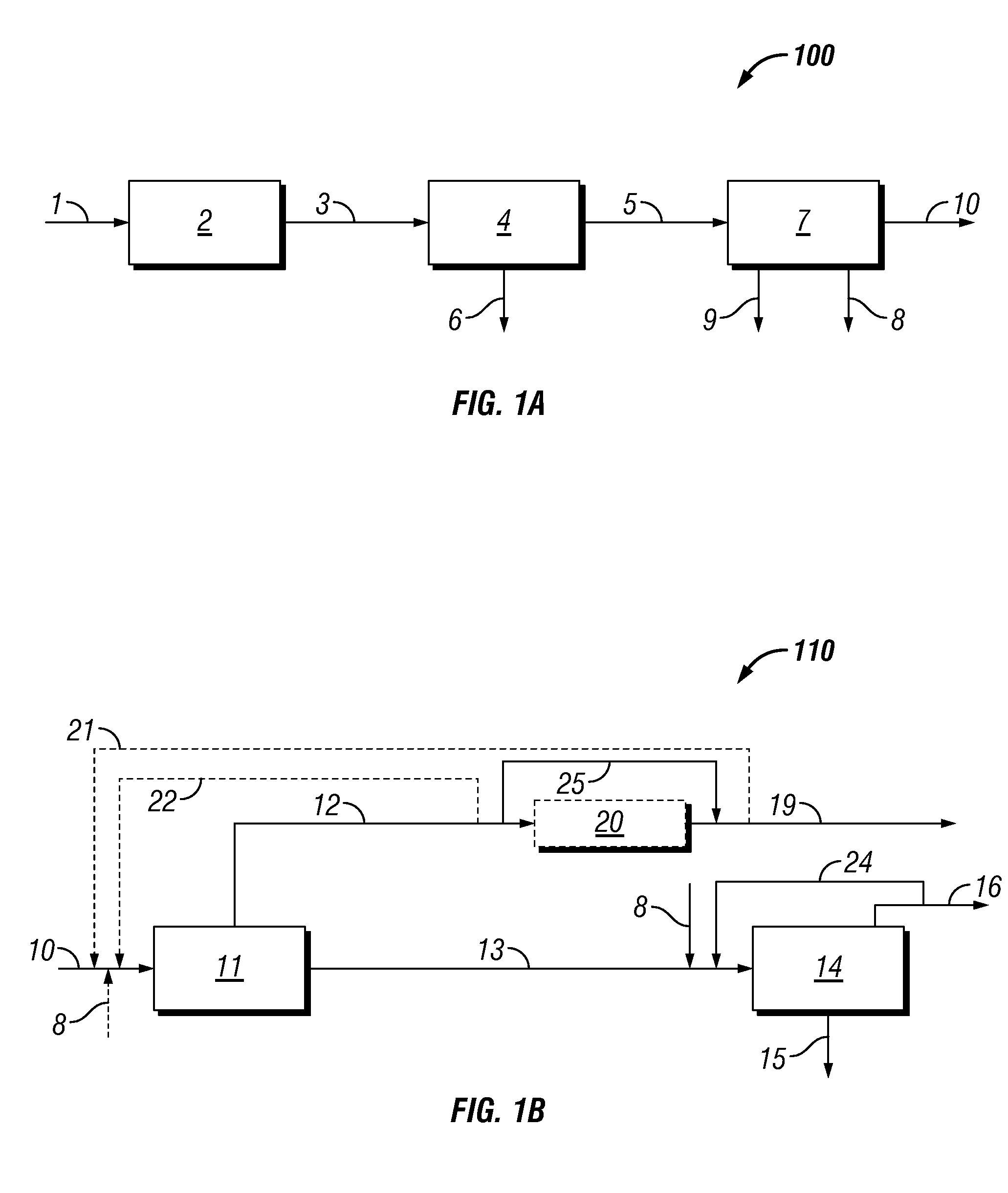
[0056]As shown in FIG. 1A, which depicts the synthesis gas produ...


PUM

PropertyMeasurementUnit
temperatureaaaaaaaaaa
weight ratioaaaaaaaaaa
mole ratioaaaaaaaaaa

Abstract

A method of utilizing hydrogen in synthesis gas production by forming synthesis gas from one or more carbonaceous materials, the synthesis gas comprising hydrogen and carbon monoxide; separating a hydrogen-rich product and a hydrogen-lean product from the synthesis gas to yield an adjusted synthesis gas product; and activating a hydrocarbon synthesis catalyst with at least a portion of the hydrogen-lean product. A system for carrying out the method is also provided, the system including at least one hydrogen extraction unit and an activation reactor operable to activate hydrocarbon synthesis catalyst, wherein the activation reactor comprises an inlet fluidly connected with the at least one hydrogen extraction unit whereby at least a portion of a hydrogen-lean gas stream, at least a portion of a hydrogen-rich gas stream, or at least a portion of both may be introduced into the activation reactor.

Description

CROSS-REFERENCE TO RELATED APPLICATIONS[0001]This application claims the benefit under 35 U.S.C. §119(e) of U.S. Provisional Patent Application No. 60 / 971,059 filed Sep. 10, 2007, the disclosure of which is hereby incorporated herein by reference.STATEMENT REGARDING FEDERALLY SPONSORED RESEARCH OR DEVELOPMENT[0002]Not applicable.BACKGROUND[0003]1. Field of the Invention[0004]This invention relates generally to the field of synthetic fuel (synfuel) production. Specifically, the invention relates to a method of maximizing hydrogen and carbon utilization in synfuel production using carbonaceous material as primary feedstocks.[0005]2. Background of the Invention[0006]There are many processes known in the art for converting hydrocarbon sources such as natural gas, coal, coke, bio-mass, etc., into more valuable hydrocarbon products. A typical conversion process involves first converting the hydrocarbon source into synthesis gas or syngas, which is a mixture of primarily carbon monoxide an...

Claims


Application Information

Patent Timeline
Patent Type & Authority Patents(United States)
IPC IPC(8): C01B3/36C01B6/24C01B3/02C10J3/46B01J7/00C07C27/00C07C27/06
CPCB01J37/16C01B3/34C01B3/56C10G2/332C10G45/60C10G47/02C10G49/02C10J3/00C10K3/00B01J37/18C10G2300/703C01B2203/0405C01B2203/043C01B2203/046C01B2203/0485C01B2203/049C01B2203/062C10J2300/0916C10J2300/093C10J2300/0943C10J2300/1618C10J2300/1659C10J2300/1823C10G2300/1011Y02P20/145Y02P30/20Y02P20/52
Inventor MOHEDAS, SERGIOIBSEN, MARK
Owner RES USA LLC
Why Eureka
Try Eureka