
Information recording medium and method for manufacturing same

a technology of information recording medium and manufacturing method, which is applied in the direction of optical recording/reproducing/erasing method, photomechanical apparatus, instruments, etc., can solve the problems of difficult to maintain a constant thickness of tiosub>2 /sub>film, and take a longer time to manufacture information recording medium, etc., to achieve high transmittance, high refractive index, and stable and efficient deposited

Inactive Publication Date: 2012-01-03
PANASONIC CORP
View PDF8 Cites 0 Cited by
  • Summary
  • Abstract
  • Description
  • Claims
  • Application Information

AI Technical Summary

Benefits of technology

"The present invention provides an information recording medium with a stable and high deposition rate transmittance adjusting layer that has a high refractive index comparable to conventional ones. The method of manufacturing the information recording medium includes depositing a recording layer, a reflective layer, and a transmittance adjusting layer in a specific order using a target containing Nb, oxygen, and at least one element M selected from Ti, Zr, Hf, Y, Cr, Zn, Ga, Co, Bi, In, Ta, and Ce. The transmittance adjusting layer contains Nb, oxygen, and at least one element M selected from Ti, Zr, Hf, Y, Cr, Zn, Ga, Co, Bi, In, Ta, and Ce. The method allows for the efficient and stable deposition of a high refractive index transmittance adjusting layer, resulting in a high transmittance information recording medium with good recording / reproducing characteristics."

Problems solved by technology

However, TiO2 caused problems in that it takes a longer time to manufacture an information recording medium since it has a low deposition rate during sputtering and a great variation in deposition rate due to moisture, and it is difficult to maintain a constant thickness of the TiO2 film.

Method used


Image

  • Information recording medium and method for manufacturing same
  • Information recording medium and method for manufacturing same
  • Information recording medium and method for manufacturing same

Examples


embodiment 1

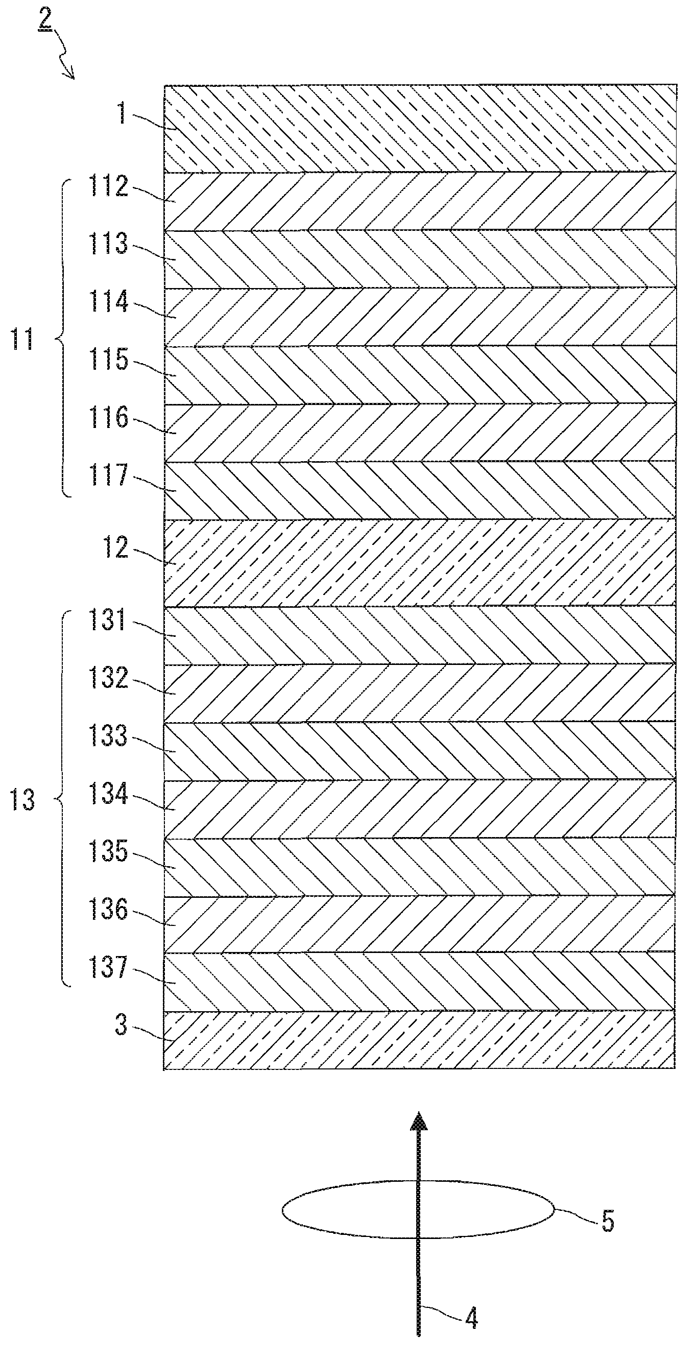
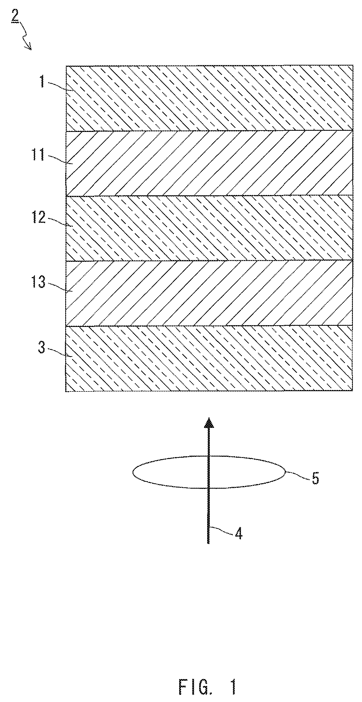
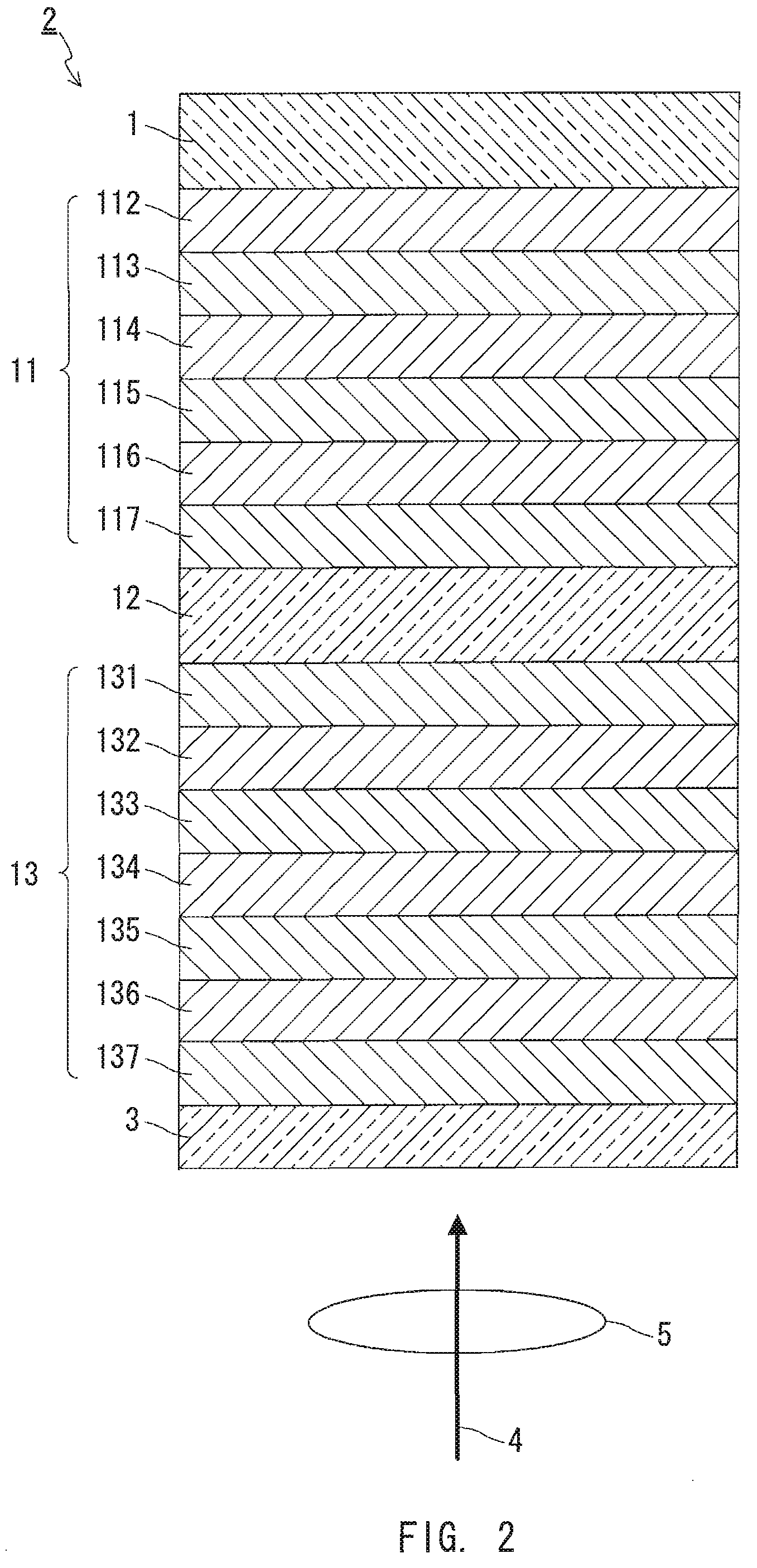
[0033]In Embodiment 1, an example of an information recording medium of the present invention is described. FIG. 1 shows a partial sectional view of an information recording medium of Embodiment 1. The information recording medium 2 of this embodiment is an optical information recording medium that can record and reproduce information through irradiation with a laser beam 4 focused through an objective lens 5.

[0034]The information recording medium 2 includes a first information layer 11, a separation layer 12, a second information layer 13, and a transparent layer 3 on a substrate 1 in this order. That is, the information recording medium 2 of this embodiment is an example obtained when N=2 and L=2 in the information recording medium of the present invention, and the second information layer 13 corresponds to the N-th information layer and the L-th information layer. Furthermore, in the information recording medium 2 of this embodiment, the transparent layer 3 side is the laser beam...

embodiment 2

[0100]In Embodiment 2, another example of an information recording medium of the present invention is described. FIG. 5 shows a partial sectional view of the information recording medium according to Embodiment 2. The information recording medium 8 of this embodiment is an optical information recording medium that can record and reproduce information through irradiation with a laser beam 4 focused through an objective lens 5 as in the case of the information recording medium 2 described in Embodiment 1.

[0101]The information recording medium 8 has a structure in which a second information layer 13 and a first information layer 11 are stacked on a first substrate 53 and a second substrate 51, respectively, and the first information layer 11 and the second information layer 13 are bonded to each other with an adhesive layer 52 being interposed therebetween. That is, the information recording medium 8 of this embodiment is an example obtained when N=2 and L=2 in the information recordin...

embodiment 3

[0129]In Embodiment 3, another example of an information recording medium of the present invention is described. FIG. 9 shows a partial sectional view of the information recording medium according to Embodiment 3. The information recording medium 15 of this embodiment is an optical information recording medium that can record and reproduce information through irradiation with a laser beam 4 focused through an objective lens 5 as in the case of the information recording medium 2 described in Embodiment 1.

[0130]The information recording medium 15 is formed by stacking a second information layer 13, a separation layer 12, and a first information layer 11 on a substrate 55 and bonding the first information layer 11 and a dummy substrate 60 together, with an adhesive layer 52 being interposed therebetween. That is, the information recording medium 15 of this embodiment has a structure obtained when N=2 and L=2 in the information recording medium of the present invention, and the second i...


PUM

PropertyMeasurementUnit
thicknessaaaaaaaaaa
thicknessaaaaaaaaaa
transmittanceaaaaaaaaaa

Abstract

An information recording medium of the present invention includes N information layers on a substrate (1), where N is an integer of 2 or more. Information is recorded / reproduced by irradiating each of the information layers (11, 12) with a laser beam (4). When the N information layers are referred to as a first information layer to an N-th information layer sequentially from the opposite side to a laser beam incident side, the L-th information layer included in the N information layers includes at least a recording layer (135) capable of undergoing a phase change through laser beam irradiation, a reflective layer (132), and a transmittance adjusting layer (131) in this order from the laser beam incident side, where L is an integer satisfying 2≦L≦N. The transmittance adjusting layer (131) contains Nb, oxygen (O), and at least one element M selected from Ti, Zr, Hf, Y, Cr, Zn, Ga, Co, Bi, In, Ta, and Ce. In the transmittance adjusting layer (131), the content of Nb is at least 2.9 atom %.

Description

TECHNICAL FIELD[0001]The present invention relates to information recording media for recording and reproducing information through laser beam irradiation, and methods of manufacturing the same.BACKGROUND ART[0002]When a thin film formed of, for example, a chalcogen material deposited on a substrate is irradiated with a laser beam and thereby is heated locally, the difference in irradiation conditions makes it possible to cause a phase change between states with different optical constants. Information recording media that utilize this phenomenon are researched / developed and commercialized widely.[0003]Among the information recording media that utilize the phase change, an optical recording medium allows signals to be recorded through modulation of output power of a laser beam between at least two power levels. Suitable selection of the power level makes it possible to record a new signal simultaneously while erasing a signal that has been recorded.[0004]The inventors disclosed an o...

Claims


Application Information

Patent Timeline
Patent Type & Authority Patents(United States)
IPC IPC(8): B32B3/02G11B7/24G11B7/24038G11B7/243G11B7/2433G11B7/254G11B7/257
CPCG11B7/24G11B7/24038G11B7/243G11B7/257G11B7/266G11B7/00454Y10T428/21G11B2007/25706G11B2007/25708G11B2007/25715G11B7/258
Inventor TAKAOKA, TOMOYASUSAKAUE, YOSHITAKAKOJIMA, RIE
Owner PANASONIC CORP
Learn More