
Three-phase square-wave permanent magnet brushless DC motor

a permanent magnet, brushless technology, applied in the direction of dynamo-electric machines, magnetic circuit rotating parts, magnetic circuit shapes/forms/construction, etc., can solve the problems of large commutated torque ripple, large increase in complexity of control systems, and inapplicable effects in practical applications that were not satisfying, etc., to achieve high performance, low cost, and new structure

Active Publication Date: 2012-01-03
SCBD (ANHUI) E TECH CO LTD
View PDF30 Cites 16 Cited by
  • Summary
  • Abstract
  • Description
  • Claims
  • Application Information

AI Technical Summary

Benefits of technology

"This patent is about a new type of square-wave permanent magnet motor that solves problems with existing motors. The motor has a new structure and performs better than previous motors. It has a three-phase design with many pairs of permanent magnets and three-phase windings. The motor has a high performance and low cost. The technical effects of this patent include a new motor design that solves previous problems, a new stator core design that improves performance, and a new method of manufacturing the stator core that reduces costs."

Problems solved by technology

But, it has a biggest disadvantage that there is great principle commutated torque ripple.
Therefore, researchers put forward many compensation measures, whose effects in practical application were not satisfying.
However, the sine-wave permanent magnet motor will induce a great rise in complexity of the control system and a substantial increase of cost and what is more important is the great falling of the energy index of the motor.
Due to the said disadvantage, its application is limited in occasions with lower demand, and the study on it has been rare at home and abroad.

Method used


Image

  • Three-phase square-wave permanent magnet brushless DC motor
  • Three-phase square-wave permanent magnet brushless DC motor
  • Three-phase square-wave permanent magnet brushless DC motor

Examples


Embodiment Construction

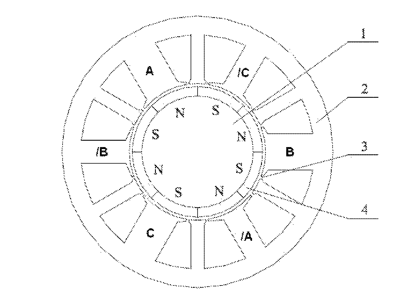
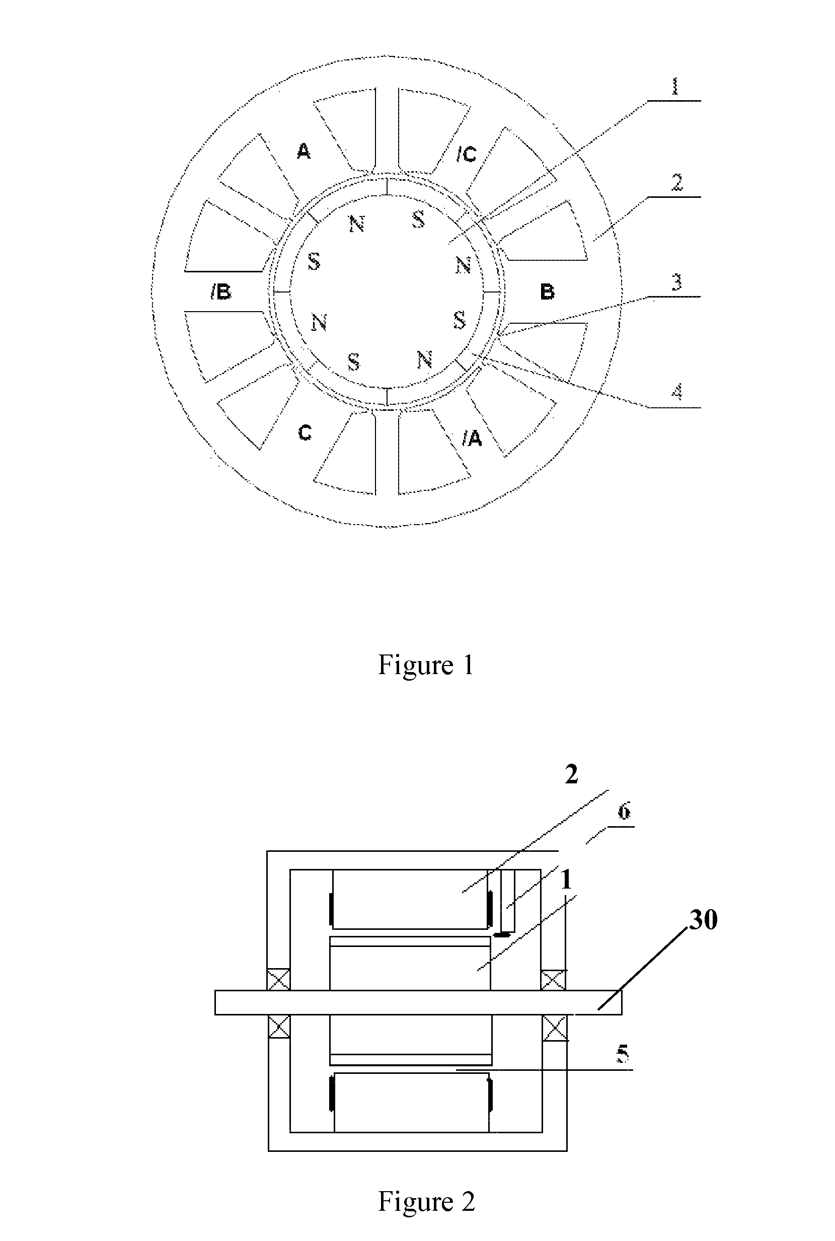
[0027]An preferred example in this invention is indicated in FIG. 1 and FIG. 2. In FIG. 2, the main structure of this three-phase permanent magnet brushless DC motor is indicated, whose main components comprise a rotor 1, a stator 2, a shaft 30 and so on, and physical air-gap 5 between the rotor 1 and the stator 2 is 0.2-2 mm. The magnetic sensitive direction of a hall position sensor is consistent with the direction of the rotor normal. The hall position sensor is installed on the stator frame 6 with the distance of 1˜3 mm air-gap from the outer circle of the rotor permanent magnetic steel (the permanent magnet).

[0028]In FIG. 1, a permanent magnet 4 with many pairs of poles on the rotor core produces air-gap magnetic field; in FIG. 1, there are 4 pairs of the permanent magnets with 8 magnetic poles N, S arranged alternately, that is, the number 2P of magnetic poles of the rotor is 8. In practical implementation, the permanent magnet 4 can be the tegular magnetic steel with radial-m...


PUM


Abstract

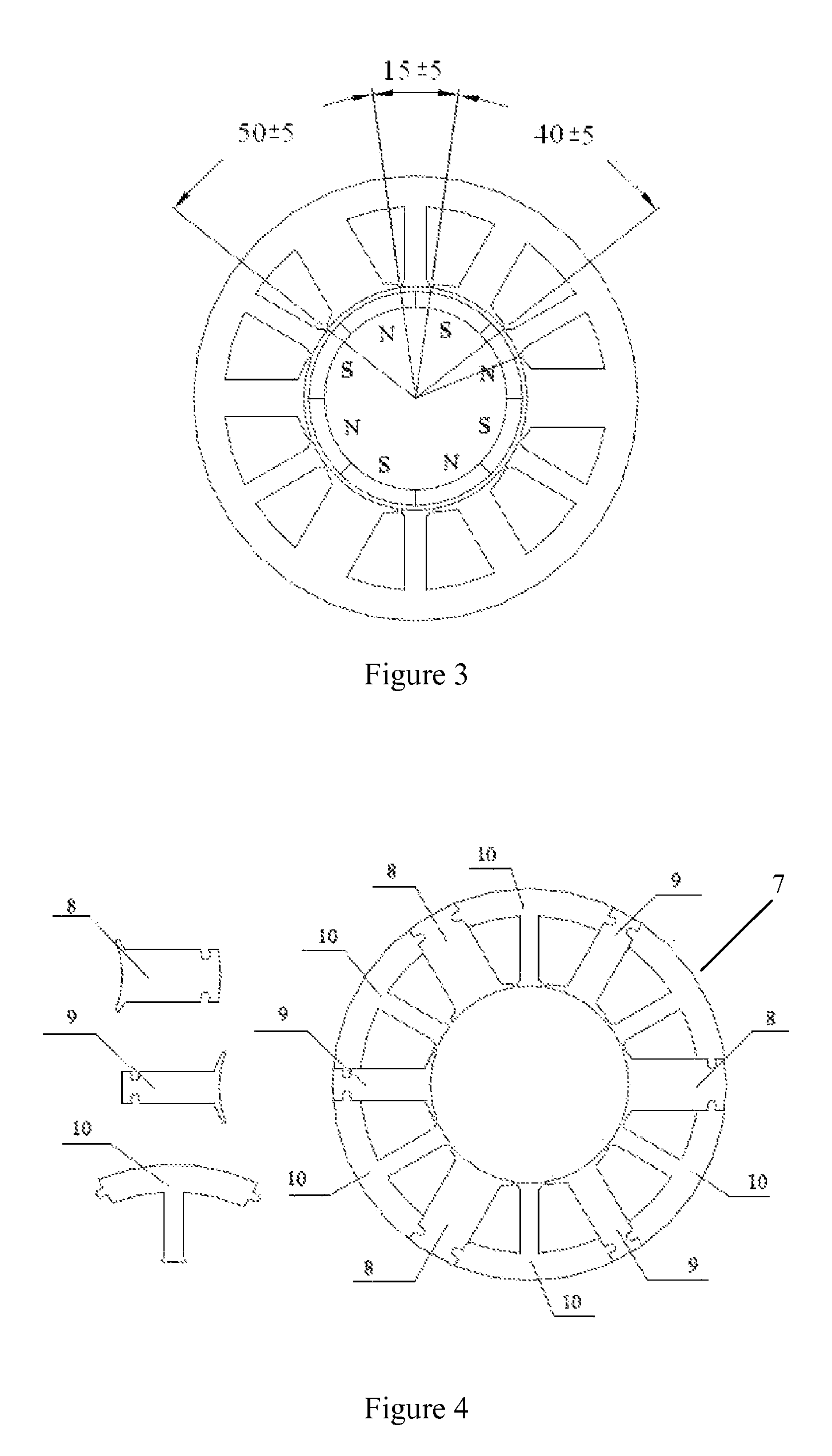
This invention relates to a three-phase square-wave permanent magnet brushless DC motor for solving problems of the existing square-wave permanent Magnet Motor and sine-wave permanent magnet motor. In this invention, the number 2P of magnetic poles on the said rotor core is 8; the slot number Z of the said stator core is 12, accordingly there are 12 teeth, including three big teeth, three medium teeth and six small teeth; the ratio of their mechanical angles is 50° (±5°) for big teeth: 40° (±5°) for medium teeth: 15° (±5°) for small teeth, and the sum of the mechanical angles of one big tooth, one medium tooth and two small teeth must be 120°. Three-phase concentrated windings are respectively wound on the big teeth and the medium teeth, in which there are only two concentrated windings for each phase, thus there are only 6 concentrated windings for the three-phase motor. With driven by three-phase square-wave current, the said motor can produce a smooth torque which ripple index corresponds to that of the sine-wave permanent magnet servo motor, at the same time, it also has a plurality of advantages including windings end minimization, air-gap minimization, material minimization, cogging torque minimization and loss minimization and so on.

Description

CROSS REFERENCE TO RELATED PATENT APPLICATION[0001]This application claims the priority of the Chinese patent application No. 200720172743.2 filed on Oct. 29, 2007, which application is incorporated herein by reference.FIELD OF THE INVENTION[0002]This invention relates to a permanent magnet motor, in particular a three-phase square-wave permanent magnet brushless DC motor, which is applicable for direct drive and position and rate servo-control system.BACKGROUND ART[0003]The permanent magnet motor can be classified into the sine-wave motor and the square-wave motor, according to its drive current and back-EMF waveform. The sine-wave permanent magnet motor is generally known as permanent magnet synchronous motor (PMSM), or the sine-wave AC servo motor. The square-wave permanent magnet motor is known as square-wave brushless DC motor (BLDCM).[0004]During the 1980's, the square-wave permanent magnet motor was widely applied, whose external characteristics are almost the same as that of...

Claims


Application Information

Patent Timeline
Patent Type & Authority Patents(United States)
IPC IPC(8): H02K1/06
CPCH02K1/148H02K21/16H02K29/03
Inventor LI, TIECAIQI, YAMEIZHOU, ZHAOYONGKONG, XIANGLAN, WEILONGXU, FEIPENG
Owner SCBD (ANHUI) E TECH CO LTD
Learn More