
Chip package and manufacturing method thereof

a technology of chip and manufacturing method, applied in the field of semiconductor devices, can solve the problems of serious and challenging problems of electronic devices or systems, such as electromagnetic interference (emi), and achieve the effect of less effort and better design flexibility

Active Publication Date: 2012-01-10
ADVANCED SEMICON ENG INC
View PDF91 Cites 63 Cited by
  • Summary
  • Abstract
  • Description
  • Claims
  • Application Information

AI Technical Summary

Benefits of technology

[0007]In view of the foregoing, the present invention provides a manufacturing method of a chip package, which offers better design flexibility with less effort.
[0008]The present invention is further directed to a chip package with enhanced effectiveness of EMI shielding.
[0013]According to one embodiment of the present invention, the connectors can be arranged on sawing lines of the matrix substrate and on boundary lines of each substrate unit, so that the singulation process cuts through the connectors and the matrix substrate. Alternatively, the connectors can be arranged around boundary lines of each substrate unit with a distance apart, so that the singulation process does not cut through the connectors.
[0017]Based on the above, the shielding layer and the studs disposed on the substrate functions as an EMI shield of the chip package. According to the present invention, owning to the flexible and variable design of the shielding layer and the studs, the process window can be improved.

Problems solved by technology

Electro-magnetic interference (EMI) is a serious and challenging problem for most electronic devices or systems.
Conventionally, EMI shielding solutions typically involve the use of metal plates and / or conductive gaskets, which are later attached or affixed at higher manufacturing costs.

Method used


Image

  • Chip package and manufacturing method thereof
  • Chip package and manufacturing method thereof
  • Chip package and manufacturing method thereof

Examples


Embodiment Construction

[0027]Reference will now be made in detail to the present preferred embodiments of the invention, examples of which are illustrated in the accompanying drawings. Wherever possible, the same reference numbers are used in the drawings and the description to refer to the same or like parts.

[0028]The manufacturing methods as described in the present invention can be used for fabricating various package structures and are more suitable for fabricating stacked type packages, multiple-chip packages, or high frequency device packages (including radio frequency device packages). Moreover, the manufacturing methods as described in the present invention are compatible with packaging processes utilizing build-up substrate manufacturing process or array substrate manufacturing process.

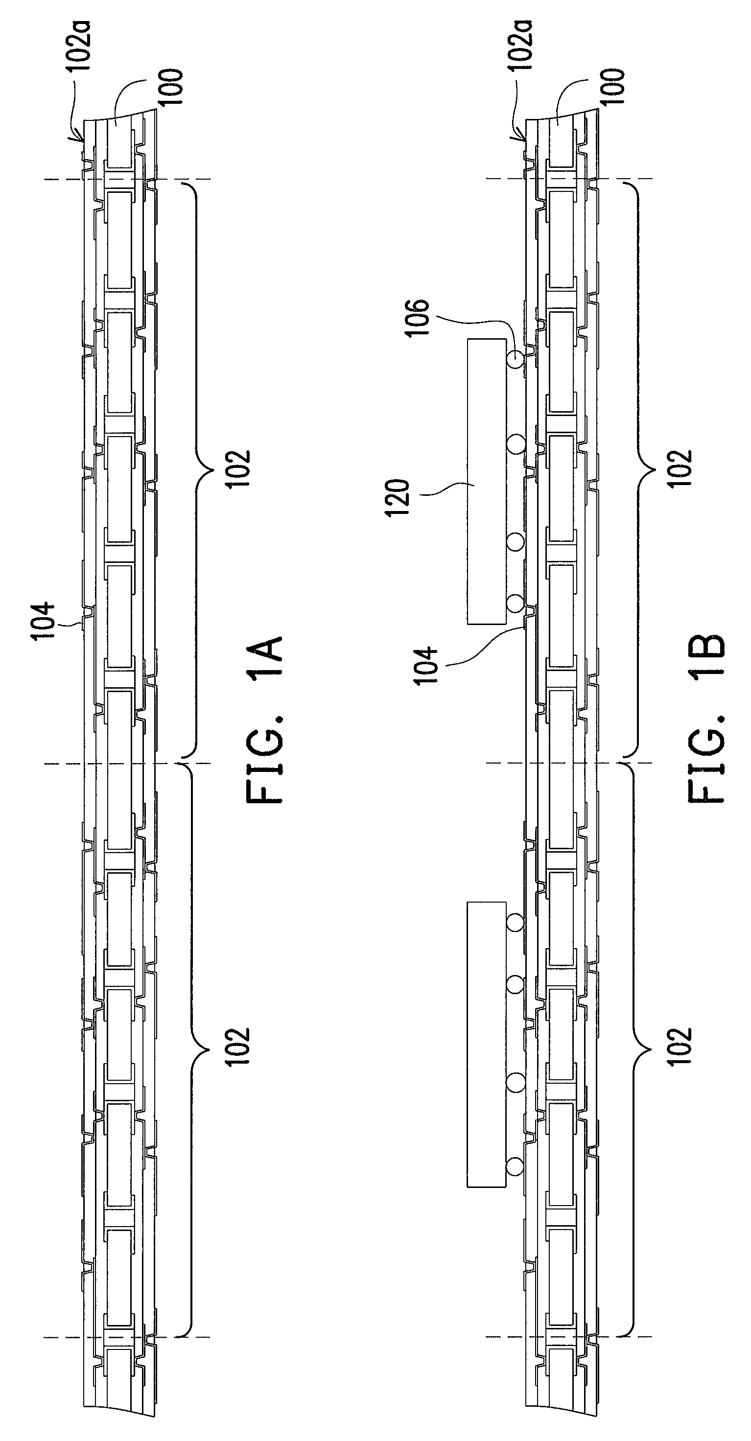
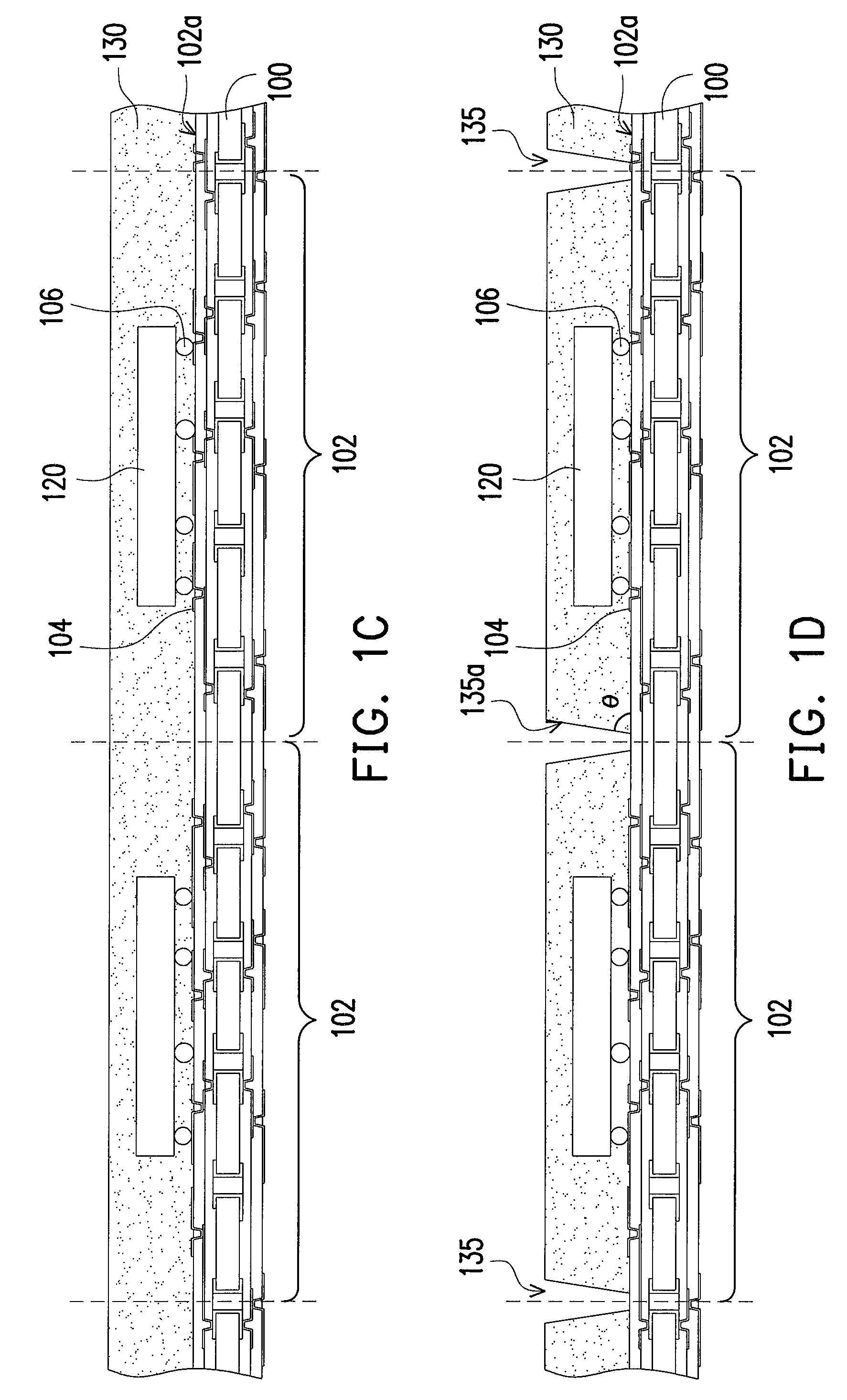
[0029]FIGS. 1A through 1F′ are schematic views showing manufacturing methods of the chip package according to the preferred embodiments of the present invention. FIGS. 1D′ and 1D″ are shown in three-dimensional sch...


PUM


Abstract

A chip package including a shielding layer having a plurality of conductive connectors for better electromagnetic interferences shielding is provided. The conductive connectors can be flexibly arranged within the molding compound for better shielding performance. The shielding layer having the conductive connectors functions as the EMI shield and the shielding layer is electrically grounded within the package structure.

Description

CROSS-REFERENCE TO RELATED APPLICATION[0001]This application claims the priority benefit of U.S. provisional application Ser. No. 61 / 109,937, filed on Oct. 31, 2008. The entirety of the above-mentioned patent application is hereby incorporated by reference herein and made a part of this specification.BACKGROUND OF THE INVENTION[0002]1. Field of the Invention[0003]The present invention relates to a semiconductor device, and more particularly to a chip package.[0004]2. Description of Related Art[0005]Electro-magnetic interference (EMI) is a serious and challenging problem for most electronic devices or systems. As EMI disturbances commonly interrupt, degrade or limit the effective performance of the electronic device or the whole circuit of the electronic system, it is necessary for the electronic devices or systems to have efficient EMI protection to ensure the effective and safe operation.[0006]EMI protection is particularly important in small-sized, densely packaged or sensitive el...

Claims


Application Information

Patent Timeline
Patent Type & Authority Patents(United States)
IPC IPC(8): H01L23/552H01L21/78
CPCH01L21/561H01L21/78H01L23/3121H01L23/552H01L24/97H05K1/0218H01L2224/16225H01L2224/97H01L2924/01013H01L2924/01029H01L2924/01033H01L2924/01047H01L2924/01078H01L2924/01079H01L2924/1815H01L2924/3025H05K3/0032H05K3/0052H05K3/284H05K2203/0415H01L2224/81H01L2924/01006H01L2924/01024H01L2924/014H01L2924/15313H01L2924/181H01L2924/14H01L2924/00014H01L2924/15311H01L2924/00011H01L2924/00H01L2224/0401
Inventor KO, DONGKYUNLEE, JUNGAN, JAESUN
Owner ADVANCED SEMICON ENG INC
Learn More