Supercharge Your Innovation With Domain-Expert AI Agents!

Connector system

a technology of connecting rods and connecting rods, applied in the direction of steering linkages, light support devices, candle holders, etc., can solve the problems of connection strength and precise alignment of objects

Active Publication Date: 2012-01-17
SOHN CHERYL L +1
View PDF21 Cites 4 Cited by
  • Summary
  • Abstract
  • Description
  • Claims
  • Application Information

AI Technical Summary

Benefits of technology

The system provides strong, flexible connections that can be easily engaged and disengaged without precise alignment, accommodating planar and non-planar objects, and supports electrical and optical communication, enhancing the versatility and stability of object mounting and interconnection.

Problems solved by technology

These examples all bear the disadvantage that the strength of the connection depends on the force required for engagement, and the correspondent force required for disengagement.
The latter two examples bear the further disadvantage that precise alignment of the objects is required in order to effect the engagement of the connectors.

Method used


Image

  • Connector system
  • Connector system
  • Connector system

Examples


Embodiment Construction

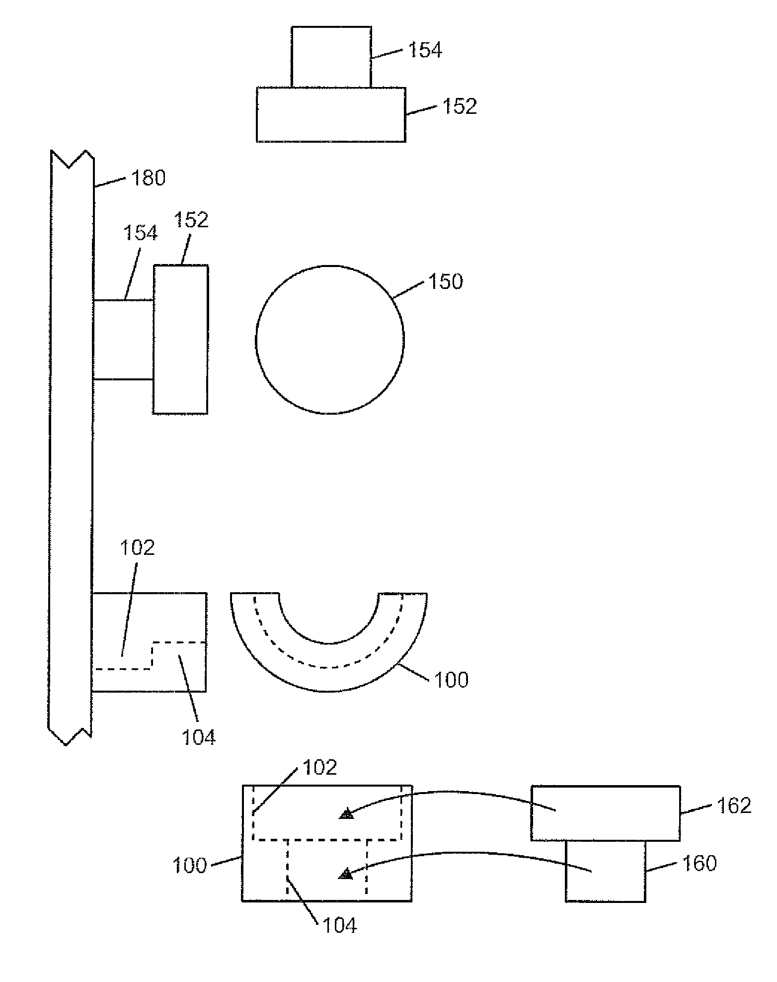
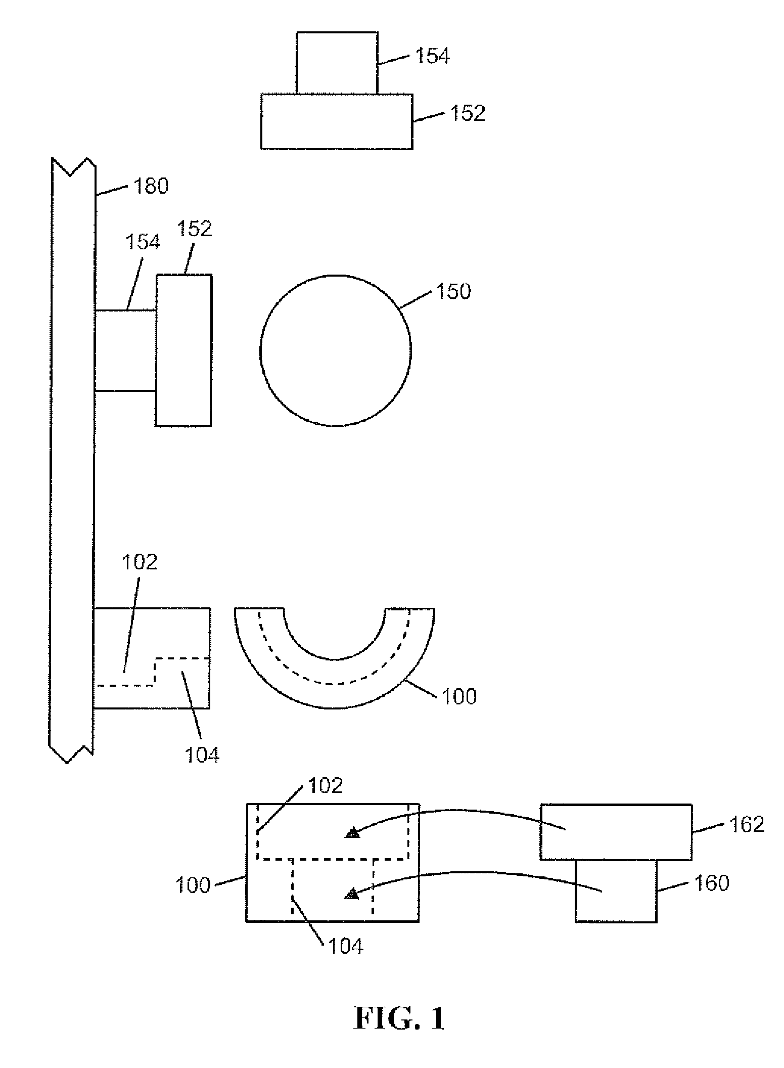
[0027]FIG. 1 shows the basic structure of a single U-shaped bracket and a flange tipped post mounted to a panel 180 which serves as a supporting surface. U-shaped bracket 100 has a lip 104 and recessed region 102. Flange tipped post 150 has stem 154 and flange 152. Also shown is a second flange tipped post 160 which can mate with U-shaped bracket 100. Flange 162 attached to mating post 160 engages into recessed region 102 of a bracket and the flange 162 is retained by lip 104. Post 150 similarly can engage with a mating bracket, not shown. Flange tipped post 160 can be attached to an object, so that engagement of the flange tipped post with U-shaped bracket 100 serves to connect the object to panel 180.

[0028]One embodiment of U-shaped bracket has the U-shape half-cylindrical and the correspondent flange tipped post cylindrical. However, adherence to purely cylindrical geometry is not a requirement of the invention. This connector system is referred to by the trademark, U-DOT.

[0029]A...


PUM


Abstract

An array of U-shaped flanged brackets and flange tipped posts attached to a supporting surface providing a mechanical connection with an object that is provided with corresponding posts and brackets. The brackets and posts can include electrical contacts or fiber optic contacts for transferring power or signals between connected objects. Various objects can be mounted on the array of brackets and posts to provide positioning flexibility.

Description

[0001]This application claims the benefit of Provisional Application No. 61 / 058,564, filed on 4 Jun. 2008.FIELD OF THE INVENTION[0002]The invention relates to connector systems for creating mechanical, electrical, and optical interconnections between objects and for mounting objects to walls and panels.BACKGROUND OF THE INVENTION[0003]Devices for making mechanical connections between objects are well known. Such devices include those which are intended to make a permanent connection, such as adhesives, weldments, solder joints, and rivets. Other known devices allow objects to be connected and disconnected repeatedly. One example of the latter is a hook and loop system such as those bearing the tradename VELCRO. Other connector systems involve mushroom-like projections which are inserted into corresponding apertures so as to resist shear movement after insertion. Other connector systems involve an array of apertures and a corresponding array of projections which are forcibly pressed ...

Claims


Application Information

Patent Timeline
Patent Type & Authority Patents(United States)
IPC IPC(8): F16M13/00
CPCA47B96/06F16B3/00F16B5/07A47F5/0807Y10T24/45476Y10T403/125Y10T24/45958Y10T403/7094Y10T24/45152Y10T24/45471Y10T403/7037Y10T403/642Y10T403/61Y10T403/28Y10T403/51F16B2200/30F16B2200/503
Inventor SOHN, CHERYL L.SOHN, DOUGLAS C.
Owner SOHN CHERYL L
Features
  • R&D
  • Intellectual Property
  • Life Sciences
  • Materials
  • Tech Scout
  • Unparalleled Data Quality
  • Higher Quality Content
  • 60% Fewer Hallucinations
Learn More