Rear-mounted aerodynamic structure for truck cargo bodies

a rear-mounted, aerodynamic technology, applied in the direction of roofs, transportation and packaging, vehicle arrangements, etc., can solve the problems of large rear aerodynamic structures, inability to integrate with the structure and function of the rear cargo doors of trucks, and inability to move upwardly, so as to achieve rapid and easy transition, reduce drag, and avoid undue effort or strength

Active Publication Date: 2012-01-24
STEMCO PROD INC
View PDF53 Cites 71 Cited by
  • Summary
  • Abstract
  • Description
  • Claims
  • Application Information

AI Technical Summary

Benefits of technology

[0010]This invention overcomes the disadvantages of the prior art by providing an aerodynamic structure attached to the rear face of a truck cargo body, which rear typically contains a door assembly, with a plurality of doors that swing open on hinges, or a single, full-width door, which rolls upwardly. The various embodiments of the invention allow an aerodynamic structure to be permanently attached to the rear of the trailer in a manner that would obscure access to the door(s) in a deployed position, in which the aerodynamic structure generates reduced drag on the trailer body, yet enables ready access to the door(s) in a folded position. The folded position still allows the rear of the trailer to be fully accessible for loading and unloading, and in the case of swinging, hinged doors (among others), allows the doors to be folded through a full 270-degree arc from a closed position to a position flush along the sides of the vehicle, with a minimal sideways projection. The various embodiments also enable relatively rapid and easy transition between the folded position and the deployed position using a variety of actuators and linkages that tie the folding and deployment of various panels of the structure together. This allows an operator to selectively fold and deploy the structure without undue effort or strength.
[0012]In another embodiment of this invention, all the panels of the aerodynamic structure portion on a given door are interconnected by hinges so that the overall tapered box defines an “origami” type of folding arrangement. In such an arrangement, a vertical, medial panel is divided into three separate panel sections with the its upper and lower panel sections joined to adjacent horizontal top and bottom surfaces. The horizontal upper and lower surfaces are, likewise, each divided diagonally into a pair of upper and lower panel sections, respectively. The opposing upper and lower panels are hingedly attached to a one-piece outer vertical panel. When either the medial panel or the outer panel is moved toward or away from the underlying truck rear face / door, the force is transmitted throughout the structure, causing it to either fold or unfold, respectively. The separate panels are joined by sliding hinges or another type of hinge assembly (such as a flexible material) that facilitates the folding of each panel over the other by allowing the joined panel to translate, as well as rotate in two degrees of freedom. This facilitates the requisite origami folding pattern by allowing movement in two degrees of freedom. This accommodates the fact that the panels have a finite thickness.
[0016]In illustrative embodiments of the present invention, the aerodynamic structure can be mounted on a door with extended hinges that either overlie conventional, original butt hinges of a retrofitted trailer door frame, or are placed remote from the original hinges. In an illustrative implementation, the hinges can be formed with a streamlined outer cover, or constructed as part of an overall, elongated butt plate with cutouts and clevis plates attached at desired locations based upon the locations of preexisting hinge clevises. The butt plate is applied to the corner of the trailer frame thereby forming a relatively continuous and streamlined rear hinge extension. The pivot axis points of the extended hinges allow for a larger swing that enable the thickened door with the folded stack-up of aerodynamic panels to open approximately 270 degrees to a position flush with the side of the trailer. This facilitates movement of the trailer into a narrow loading dock space without interference by the aerodynamic structure. The extended hinges of various embodiments can have pivot points located anywhere within an arc relative to the original hinge axis points so as to extend the swing of the door and allow the doors with folded panels to be located adjacent to the side of the trailer.
[0017]In another embodiment, instead of the above-described single axis extended hinge, the extended hinge assembly can define a multi-axis hinge having at least one central hinge clevis. This multi-axis hinge assembly provides at least two separate, parallel hinge pivots that allow the thickened door unit (with attached spacer frame and nested, folded panels) to be opened a full 270 degrees so as to lie against the adjacent side of the cargo box. In one example, at least two of the hinge assemblies on each door can be geared so as to prevent racking of the door as it swings by maintaining it within a predetermined swing pattern as defined by meshing gears in each assembly. In other examples, the doors can be conventionally hinged, using extended hinge pivots, or another type of multi-axis hinge, such as a four-bar linkage, can be employed.
[0018]In various embodiments in which the trailer employs hinged doors, lock rods are used to secure the doors near the medial joint line therebetween. To allow for clearance over these lock rods when the panel structure is folded, the panels (upper and lower, for example) can be located on hinges that define an axis with a rearwardly directed angle when folded against the door so as to provide the needed clearance. This angled fold-line allows for decreased overall stack-up at the lateral side of the door, which results in less room needed between trailers at a dock when the doors are open. The panels can be mounted to the door on hinges with pivot points remote from the inner surface of the respective panel so that the forward (trailer-frame-confronting) edge is located adjacent to the side of the trailer body / door frame for added streamlining.
[0020]The upper and lower panels of the structure can account for variability in the width of the doors, and any resulting gap by providing a medial wiper that seals between the medial facing edges of the panels to reduce / eliminate air leakage into the cavity defined by the panels. Other seals between panels, and between the panels and the door frame can also be provided. The presence of seals and other structures between the door and the frame can be accommodated by a spacer that positions the panel hinges rearwardly to overlie, for example, a preexisting door-to-frame gasket. The size of the spacer can be to allow accommodation of different-sized gaskets and differing positions for the forward end of the panel (to align its confrontation with the door frame edge).

Problems solved by technology

The flat, projecting front face of a cargo body is a substantial source of drag, above the cab roof.
Nevertheless, most attempts to provide aerodynamic structures that integrate with the structure and function of the rear cargo doors of a truck have been unsuccessful and / or impractical to use and operate.
Such rear aerodynamic structures are typically large and difficult to remove from the rear so as to access the cargo doors when needed.
However, aerodynamic structures that swing upwardly require substantial strength or force to be moved away from the doors, and also require substantial height clearance above an already tall cargo body.
While this requires less force to move, it also requires substantial side clearance—which is generally absent from a closely packed, multi-truck loading dock.
In such an environment, side-projecting or top-projecting fairings would invariably interfere with operations at the loading dock.
However, the two separate sections still present a large projection that would be incapable of swinging the requisite 270 degrees, and would undesirably tend to project into the adjacent loading bays when opened.
Because most truck doors are relatively large, being in the range of approximately 7-8 feet by 8-9 feet overall, removing, manipulating and storing a fairing in this manner may be impractical, or impossible, for the driver and loading dock staff.

Method used


Image

  • Rear-mounted aerodynamic structure for truck cargo bodies
  • Rear-mounted aerodynamic structure for truck cargo bodies
  • Rear-mounted aerodynamic structure for truck cargo bodies

Examples


Embodiment Construction

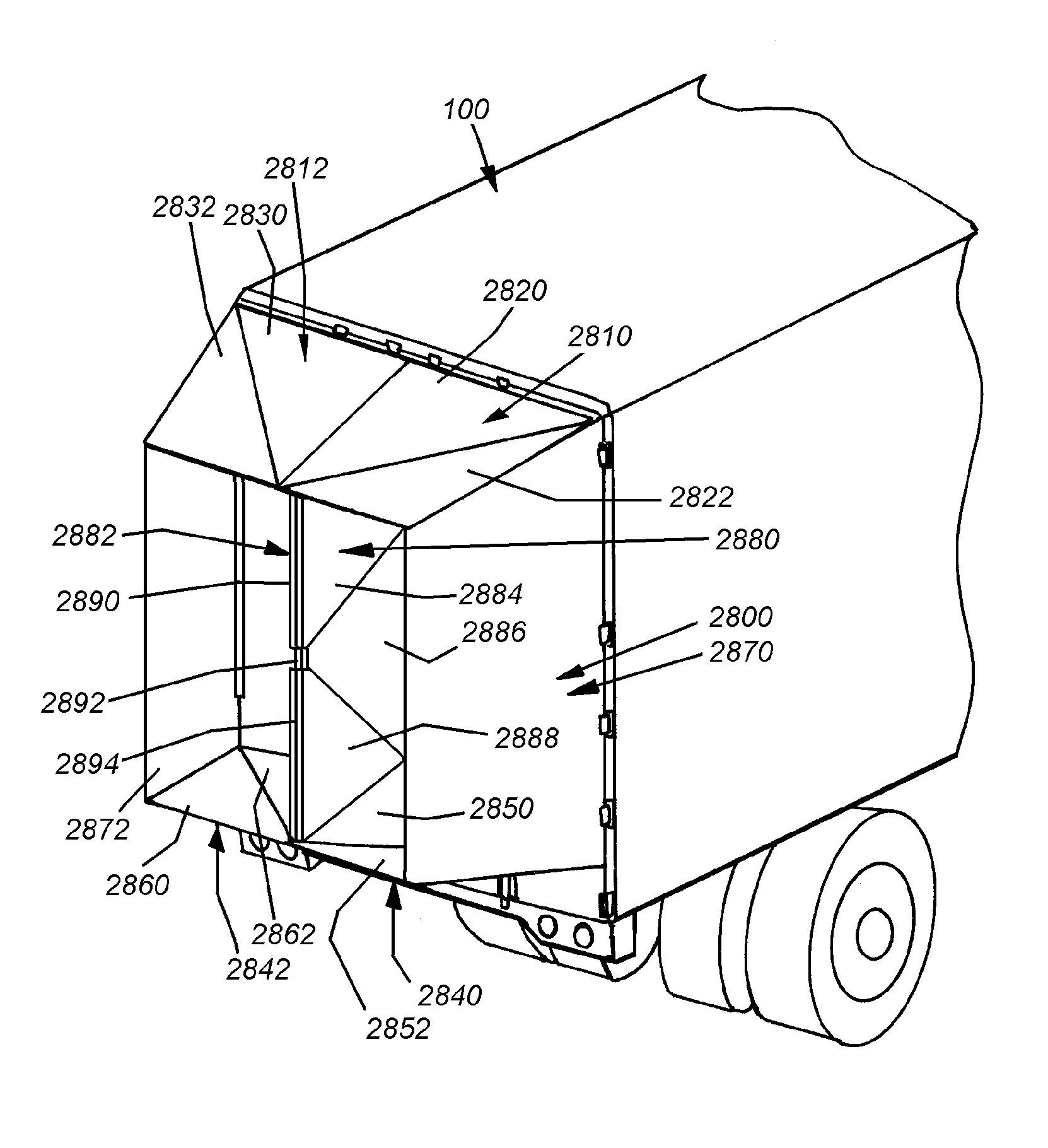
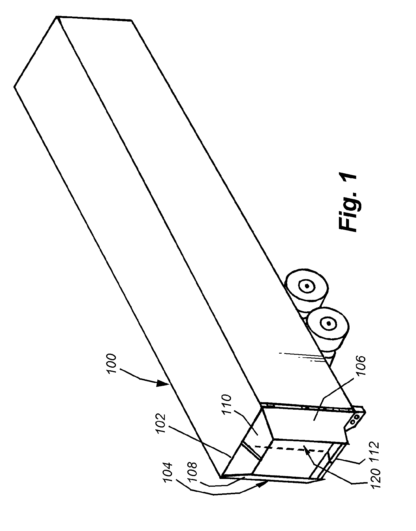
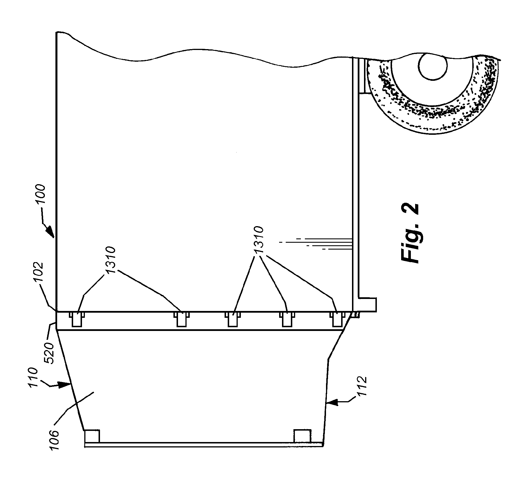
[0142]An exemplary truck trailer section 100 is shown in FIG. 1. The cab has been removed in this depiction for further clarity, but can be any acceptable size, model, type and configuration of motorized unit. It can be assumed that this cab includes appropriate roof and side aerodynamic structures to enhance the overall aerodynamic efficiency of the assembled truck. In accordance with an embodiment of this invention the trailer section includes, at its rear end 102, an aerodynamic structure 104 consisting of four inwardly tapered aerodynamic surfaces or panels 106, 108, 110 and 112. The surfaces / panels are formed from rigid, semi-rigid or somewhat-flexible sheet material that, as will be described further below, can be folded along hinge lines, or otherwise retracted, to allow access to the doors 120 that are mounted on the back 102. The thickness and perimeter shape of the panels is highly variable. In an exemplary embodiment, the panels can be formed from a lightweight metal, lik...


PUM


Abstract

This invention provides an aerodynamic structure attached to the rear face of a truck cargo body, which rear typically contains a door assembly, with a plurality of doors that swing open on hinges, or a single, full-width door, which rolls upwardly. The various embodiments of the invention allow an aerodynamic structure to be permanently attached to the rear of the trailer in a manner that would obscure access to the door(s) in a deployed position, in which the aerodynamic structure generates reduced drag on the trailer body, yet enables ready access to the door(s) in a folded position. The folded position still allows the rear of the trailer to be fully accessible for loading and unloading, and in the case of swinging, hinged doors (among others), allows the doors to be folded through a full 270-degree arc from a closed position to a position flush along the sides of the vehicle, with a minimal sideways projection. The various embodiments also enable relatively rapid and easy transition between the folded position and the deployed position using a variety of actuators and linkages that tie the folding and deployment of various panels of the structure together. This allows an operator to selectively fold and deploy the structure without undue effort or strength.

Description

CROSS-REFERENCE TO RELATED APPLICATIONS[0001]This application claims the benefit of U.S. Provisional Application Ser. No. 60 / 938,697, entitled REAR-MOUNTED AERODYNAMIC STRUCTURE FOR TRUCK CARGO BODIES and U.S. Provisional Application Ser. No. 61 / 039,411 also entitled REAR-MOUNTED AERODYNAMIC STRUCTURE FOR TRUCK CARGO BODIES, the teachings of which are expressly incorporated herein by reference.FIELD OF THE INVENTION[0002]This invention relates to aerodynamic fairings for truck bodies and other large cargo vehicles, and more particularly to aerodynamic fairings and structures that are attached to the rear of the vehicle.BACKGROUND OF THE INVENTION[0003]Trucking is the primary mode of long-distance and short-haul transport for goods and materials in the United States, and many other countries. Trucks typically include a motorized cab in which the driver sits and operates the vehicle. The cab is attached to a box-like cargo section. Smaller trucks typically include an integral cargo se...

Claims


Application Information

Patent Timeline
Patent Type & Authority Patents(United States)
IPC IPC(8): B62D35/00
CPCB62D35/001
Inventor SMITH, ANDREW F.HORRELL, CHARLES M.GROSSMANN, JEFFREY J.FELDMAN, JONATHAN R.BRUCCOLERI, ALEXANDER R.
Owner STEMCO PROD INC
Why Eureka
Try Eureka