Indexable insert for milling tools

Active Publication Date: 2012-01-24
BOEHLERIT GMBH & CO KG
View PDF33 Cites 3 Cited by
  • Summary
  • Abstract
  • Description
  • Claims
  • Application Information

AI Technical Summary

Benefits of technology

[0012]The invention relates to an indexable insert for a milling tool of the type mentioned at the outset, which causes a high chip removal and with reduced cutting forces in the tool, in particular, when used in the machining of crankshafts. The insert also has a largely positive geometry of the cutting edge, reduces the cutting pressure on the cutting faces in the area of the cutting edge, has a high manufacturing accuracy and ensures high cost effectiveness as well as insert quality in terms of manufacturing technology.
[0013]Furthermore, the invention relates to a milling tool which runs smoothly with reduced drive power consumption at a high cutting capacity.
[0017]A wedge angle of this type permits an advantageous positioning of the insert in the milling cutter and provides a high cutting edge-holding ability or a low risk of cutting edge chips in the highly stressed zones.
[0020]A chip flowing off from the cutting edge on the cutting face is subjected thereby to only a low pressure against the travel direction caused by a bending, so that wear and thermal loading are minimized. Furthermore, when the dimensional variations of the inserts are kept small and smooth cutting faces are created, the flow of chips occurs in a favorable manner during machining.
[0022]The advantages attained with a milling tool according to the invention are essentially that the indexable insert is installed in a simple manner such that a positive geometry of the cutting edge is utilized in the areas where the greatest chip removal takes place. This has advantages, in particular, by providing an efficient cutting with low cutting pressure and chatter-free with reduced power.
[0024]In this manner, fractures of the cutting edge can be effectively avoided.

Problems solved by technology

However, the negative geometry causes strong cutting forces during cutting.
Furthermore, strong cutting forces on the milling tool subject the transmission drive of the milling cutter to high loads.
However, this arrangement must be free from play and may not permit any chatter vibrations at all.
Although this geometry of the cutting edge of the insert can largely meet the expectations with respect to a reduction of the cutting forces, and thus cause a reduction of the load on the tool drive (working free from play), it has the disadvantage of being more complicated to produce, has a low cutting edge-holding ability and has an insert geometry associated with high dimensional tolerances and uneven or unmachined sintered bearing surfaces.

Method used


Image

  • Indexable insert for milling tools
  • Indexable insert for milling tools
  • Indexable insert for milling tools

Examples


Embodiment Construction

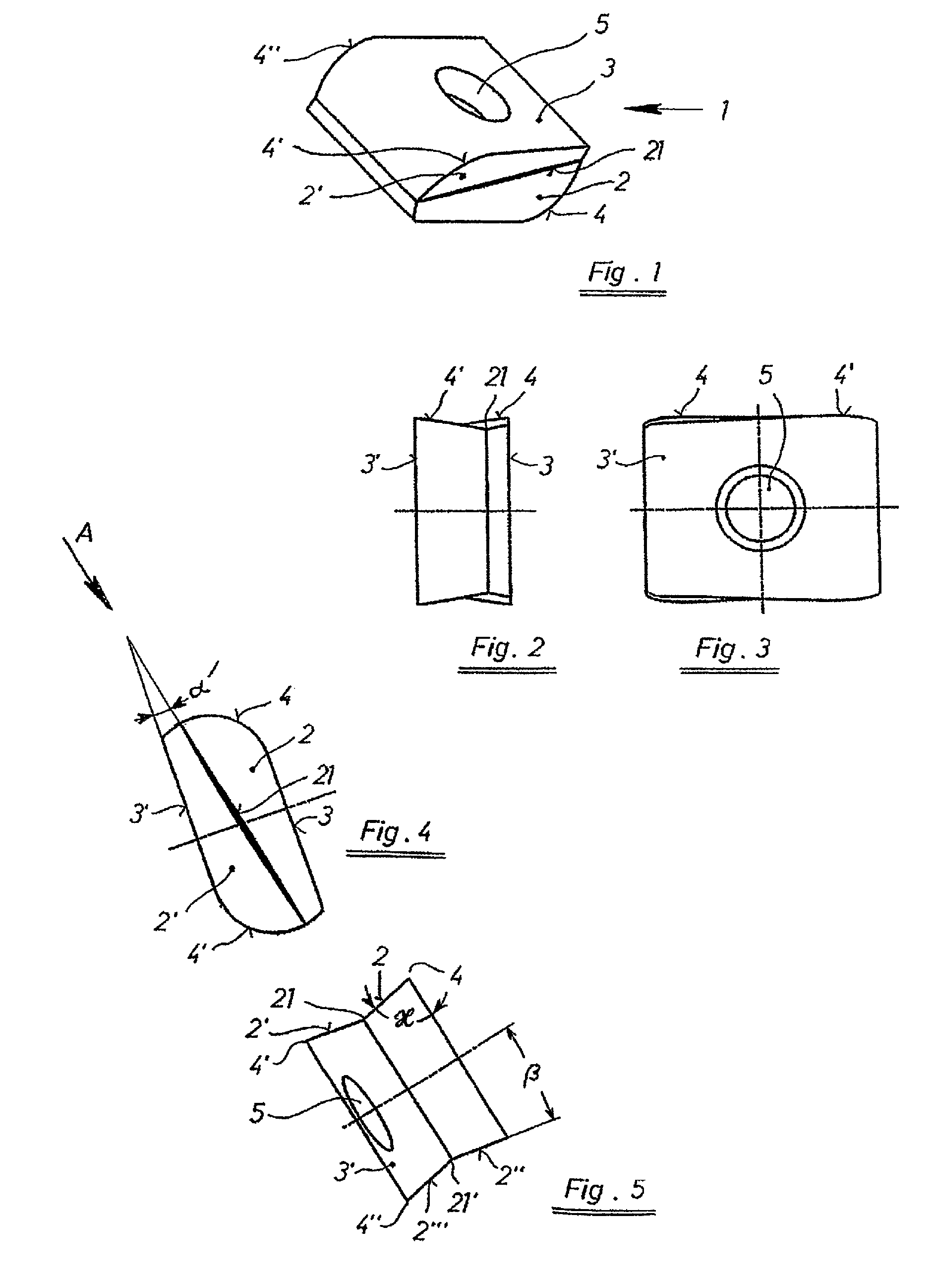
[0040]FIG. 1 shows an insert 1 having oppositely arranged mounting surfaces 3, 3′ for mounting the insert 1 on a tool. A through bore 5 is utilized for attaching the same thereto. The tangential indexable insert 1 according to an embodiment of the invention has on the front thereof a first flat cutting face 2 and a similar second cutting face 2′. These cutting faces 2, 2′ form with one another a concave end-face wedge shape and extend from a wedge base 21. The cutting faces 2, 2′ and the mounting surfaces 3, 3′ of the insert form cutting edges 4, 4′, 4″, which are curved and are arranged diagonally opposite one another. The wedge base 21 runs in a diagonally opposite manner. In this manner enlarged cutting faces 2, 2′ are formed in the curvature region.

[0041]FIG. 2 shows the insert of FIG. 1 along a direction that is parallel to the mounting surfaces 3, 3′ (or lateral surfaces). As is apparent from a comparison of FIGS. 1 and 2, the wedge base 21 runs obliquely at an angle to the la...


PUM

PropertyMeasurementUnit
Angleaaaaaaaaaa
Angleaaaaaaaaaa
Angleaaaaaaaaaa

Abstract

An indexable insert for a milling tool that includes at least one mounting surface having a through bore for fixing the insert to a rotatable tool, a rounded cutting edge defined by at least one cutting face and a lateral surface, and the at least one cutting face being arranged on a lateral side of the insert and extending from a base. The base is angled with respect to the at least one mounting surface. This abstract is not intended to define the invention disclosed in the specification, nor intended to limit the scope of the invention in any way.

Description

CROSS-REFERENCE TO RELATED APPLICATIONS[0001]The present application is a U.S. National Stage of International Patent Application No. PCT / AT2007 / 000069 filed Feb. 12, 2007 which published as WO 2007 / 101281 on Sep. 13, 2007, and claims priority of Austrian Patent Application No. A 379 / 2006 filed Mar. 7, 2006.BACKGROUND OF THE INVENTION[0002]1. Field of the Invention[0003]The invention relates to an indexable insert for a milling tool.[0004]The invention relates to an indexable insert for a milling tool for machining crankshafts or camshafts wherein the insert includes at least one mounting surface having a bore for fixing the insert to a rotatable tool part and at least one cutting face forming cutting edges with the lateral surfaces.[0005]Furthermore, the invention relates to a milling tool, in particular, a milling tool for machining crankshafts or camshafts.[0006]2. Discussion of Background Information[0007]Inserts for milling tools, in particular, milling tools for machining cran...

Claims


Application Information

Patent Timeline
IPC IPC(8): B23C5/20B23B27/22
CPCB23C3/06B23C5/207B23C2200/085B23C2200/203B23C2200/286Y10T407/2274B23C2210/0407B23C2215/20Y10T407/1936Y10T407/235B23C2200/367B23C5/202B23C5/20
Inventor KIRCHBERGER, PETER
Owner BOEHLERIT GMBH & CO KG
Why Eureka
Try Eureka