
Optical displacement gage

a technology of optical displacement and displacement amount, which is applied in the field of optical displacement gage, can solve the problems of insufficient light amount for each wavelength, narrow measurable range, and decrease in measurement accuracy, so as to reduce the occurrence of optical path differences in light propagating in the optical fiber, improve measurement accuracy of displacement amount, and improve wavelength resolution of spectroscope

Active Publication Date: 2012-01-24
KEYENCE
View PDF7 Cites 10 Cited by
  • Summary
  • Abstract
  • Description
  • Claims
  • Application Information

AI Technical Summary

Benefits of technology

The present invention provides an optical displacement gage with an expanded measurable range without lowering measurement accuracy. This is achieved by increasing the wavelength resolution of the spectroscopic unit and by raising the phase resolution of the phase determining unit. The optical displacement gage uses an absolute phase computing unit to determine the phase of the frequency component corresponding to the spatial frequency of the light intensity. The phase is determined by combining the relative phase decided within a range of 360 degrees and the past decision result. The absolute phase is obtained by combining the relative phases within a range of 60 degrees and the just previously obtained relative phase. The optical displacement gage can decide the displacement amount of the object to be measured based on the phase of the frequency component corresponding to the spatial frequency of the light intensity. The invention also includes a detection range estimating unit to estimate the detection range for the absolute phase and a structure in which a single mode optical fiber is used for transmitting the sensing light and interference light to suppress occurrence of an optical path difference and improve measurement accuracy.

Problems solved by technology

However, if the surface of the object to be measured is dirty with fingerprints or the like, there is a problem that intensity distribution of the interference light will cause a distortion, which affects measurement accuracy to decrease.
However, this type has a problem that a measurable range is narrow because it can decide the phase only in the range of 360 degrees.
In this measuring apparatus, the sensing light has a wide wavelength bandwidth so that the light amount for each wavelength is not sufficient.
Therefore, there is a problem that wavelength resolution of the spectroscope cannot be increased up to a predetermined level or higher.

Method used


Image

  • Optical displacement gage
  • Optical displacement gage
  • Optical displacement gage

Examples


Embodiment Construction

[0036](Optical Displacement Gage)

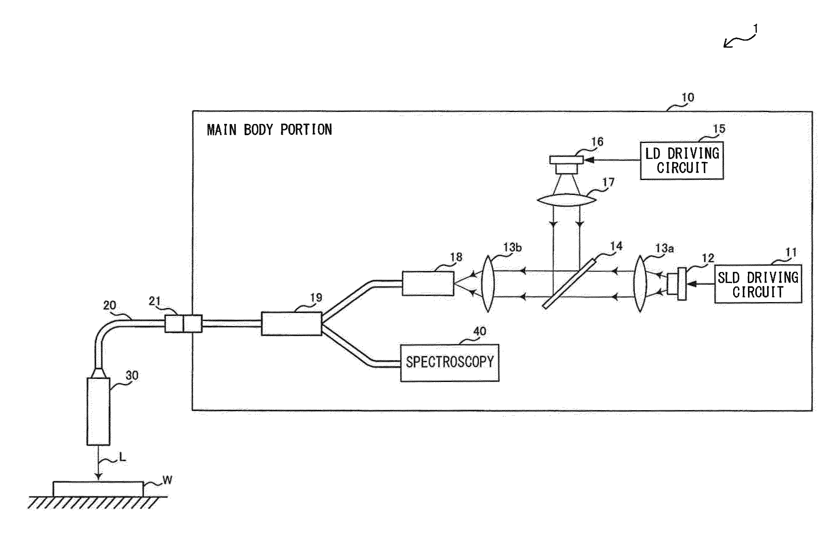
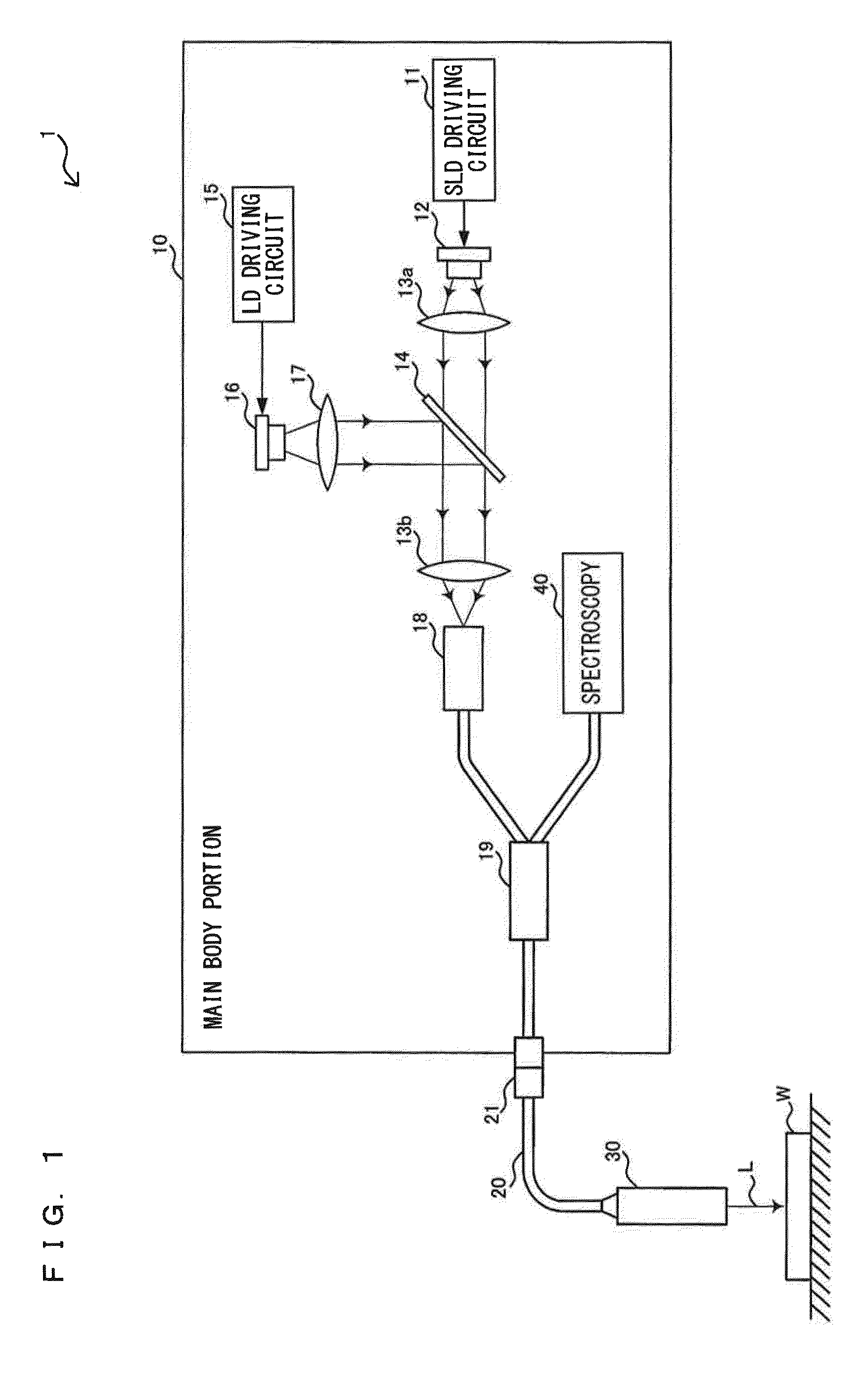
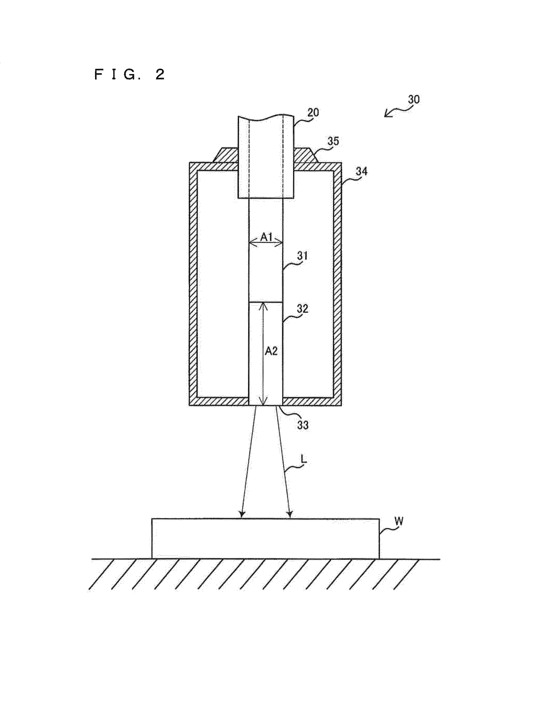
[0037]FIG. 1 is a system diagram illustrating an example of a general structure of an optical displacement gage 1 according to an embodiment of the present invention. The optical displacement gage 1 is a measuring apparatus for measuring a displacement amount of a work (object to be measured) W by using low coherent light containing various wavelengths as sensing light L for measurement. The optical displacement gage 1 includes a main body portion 10, a transmission cable 20, a connector 21 and a head portion 30.

[0038]The main body portion 10 is a processing unit which generates the sensing light L for irradiating the work W and measures a displacement amount of the work W by dispersing reflection light from the work W. The main body portion 10 includes an SLD driving circuit 11, an SLD 12, collimator lenses 13a and 17, a condensing lens 13b, a cold mirror 14, an LD driving circuit 15, an LD 16, a ferrule 18, a fiber splitter 19 and a spectroscopy 40...


PUM


Abstract

An optical displacement gage includes the phase determining unit includes a relative phase deciding unit to decide a relative phase of the frequency component within a range of 360 degrees, an absolute phase computing unit to compute an absolute phase by combining the relative phase based on the decision result by the relative phase deciding unit and the past decision result by the relative phase, and a phase reference updating unit to update a reference point of the absolute phase based on a reset instruction, and the displacement amount deciding unit decides the displacement amount based on the absolute phase.

Description

CROSS-REFERENCE TO RELATED APPLICATIONS[0001]The present application claims foreign priority based on Japanese Patent Application No. 2008-293851, filed Nov. 17, 2008, the contents of which is incorporated herein by reference.BACKGROUND OF THE INVENTION[0002]1. Field of the Invention[0003]The present invention relates to an optical displacement gage, and more specifically, relates to improvements of an optical displacement gage for measuring a displacement amount of an object to be measured by utilizing interference between reflection light reflected from a reference surface and reflection light reflected from the object to be measured.[0004]2. Description of the Related Art[0005]Conventionally, there is known a film thickness measuring apparatus for measuring thickness of a transparent film by irradiating the transparent film with wide-band light containing various wavelengths as sensing light for measurement, and by dispersing the interference light of reflection light reflected o...

Claims


Application Information

Patent Timeline
Patent Type & Authority Patents(United States)
IPC IPC(8): G01B9/02G01B11/02
CPCG01B11/026
Inventor AKISHIBA, YUJI
Owner KEYENCE
Learn More