Method for determining the temporal position of a wave packet and flow measuring device

a technology of flow measurement and wave packet, which is applied in the field of determining the temporal position of a wave packet and a flow measuring device, can solve problems such as complicated construction, and achieve the effect of increasing the accuracy of propagation time measurement and less expensive components

Active Publication Date: 2012-01-24
VYAIRE MEDICAL GMBH
View PDF21 Cites 57 Cited by
  • Summary
  • Abstract
  • Description
  • Claims
  • Application Information

AI Technical Summary

Benefits of technology

[0035]It is the object of the invention to allow the use of less expensive components and / or to increase the accuracy of the propagation time measurement by means of an intelligent evaluation method.
[0038]An advantage of using a weighted sum of measured values of a wave packet for determining the temporal position of the wave packet is that, by this, a great portion of the energy of the wave packet is evaluated, so that the temporal uncertainty becomes small and the temporal position can be determined very exactly.
[0040]The use of a sine and a cosine function as compare functions is advantageous because the position of the wave packet within a period can thus be determined with the aid of an arc tangent function, without the calculation of other compare functions.
[0041]The use of an exponential envelope, which is similar to a bell-shaped curve, fits the total shape of the compare function to the shape of a wave packet. Thus, it is possible to evaluate practically the total energy of the wave packet and to determine the temporal position with an optimum accuracy.
[0042]The iterative calculation of the temporal position of a wave packet reduces the number of the necessary calculations of product sums and can, thus, save calculation time.
[0045]A maximum search in product sums of measured values by means of a compare function shifted by a different distance makes it possible to keep the program code short.

Problems solved by technology

A disadvantage is the complicated construction as well as eddies which occur in the transition range between the vertical and the horizontal legs.
The Fourier transformation is predestinated to provide global information about a signal f(t) because its base functions extend over the entire time domain and do not allow any temporal locating ability.

Method used


Image

  • Method for determining the temporal position of a wave packet and flow measuring device
  • Method for determining the temporal position of a wave packet and flow measuring device
  • Method for determining the temporal position of a wave packet and flow measuring device

Examples


Embodiment Construction

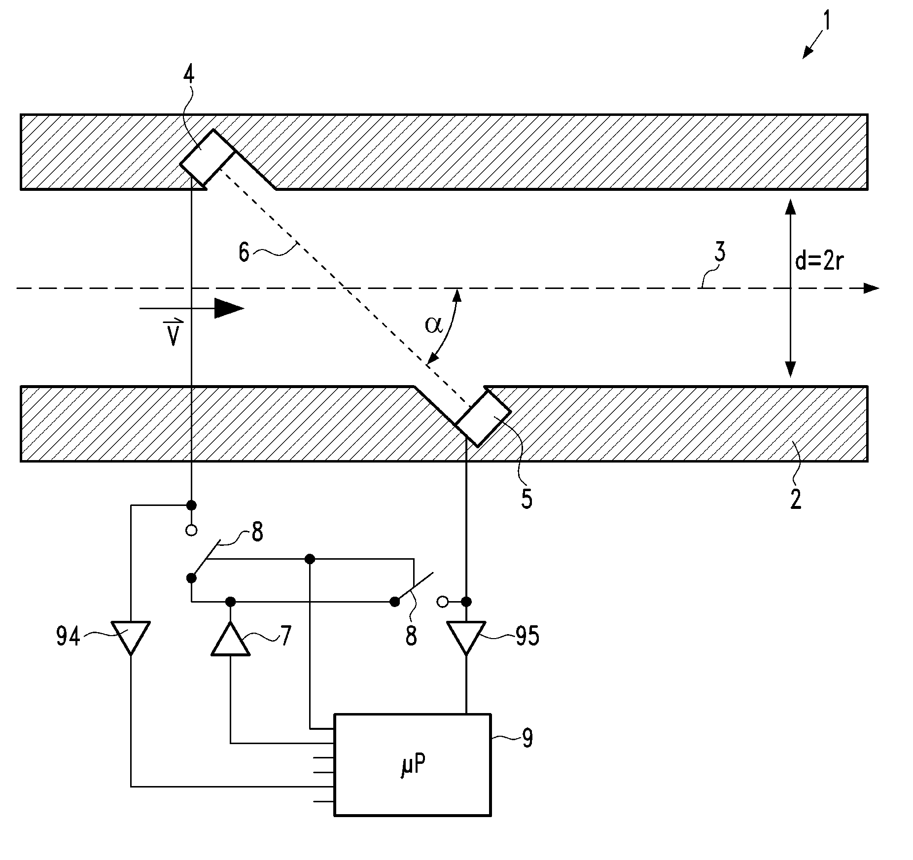
[0060]As can be seen from the above formulae, in particular formula (8), especially the propagation time difference Δt and the mean propagation time t0 must be measured as exactly as possible. The other quantities entering the flow rate {dot over (V)}, i.e. C1, C2, L, α, and / or r, are largely constant and can be determined either directly or by means of calibration measurements. Also the non-linearities, which entail that C1 and C2 depend on {dot over (V)} and, thus, on Δt, can be gotten under control by standard measurements and the fitting of model curves, e.g. polynomials, to the measured values.

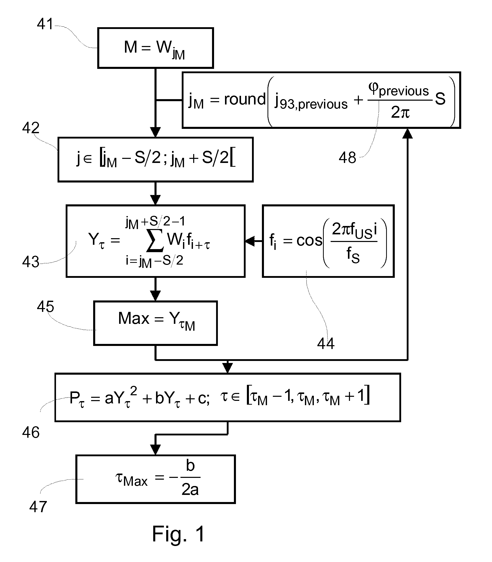
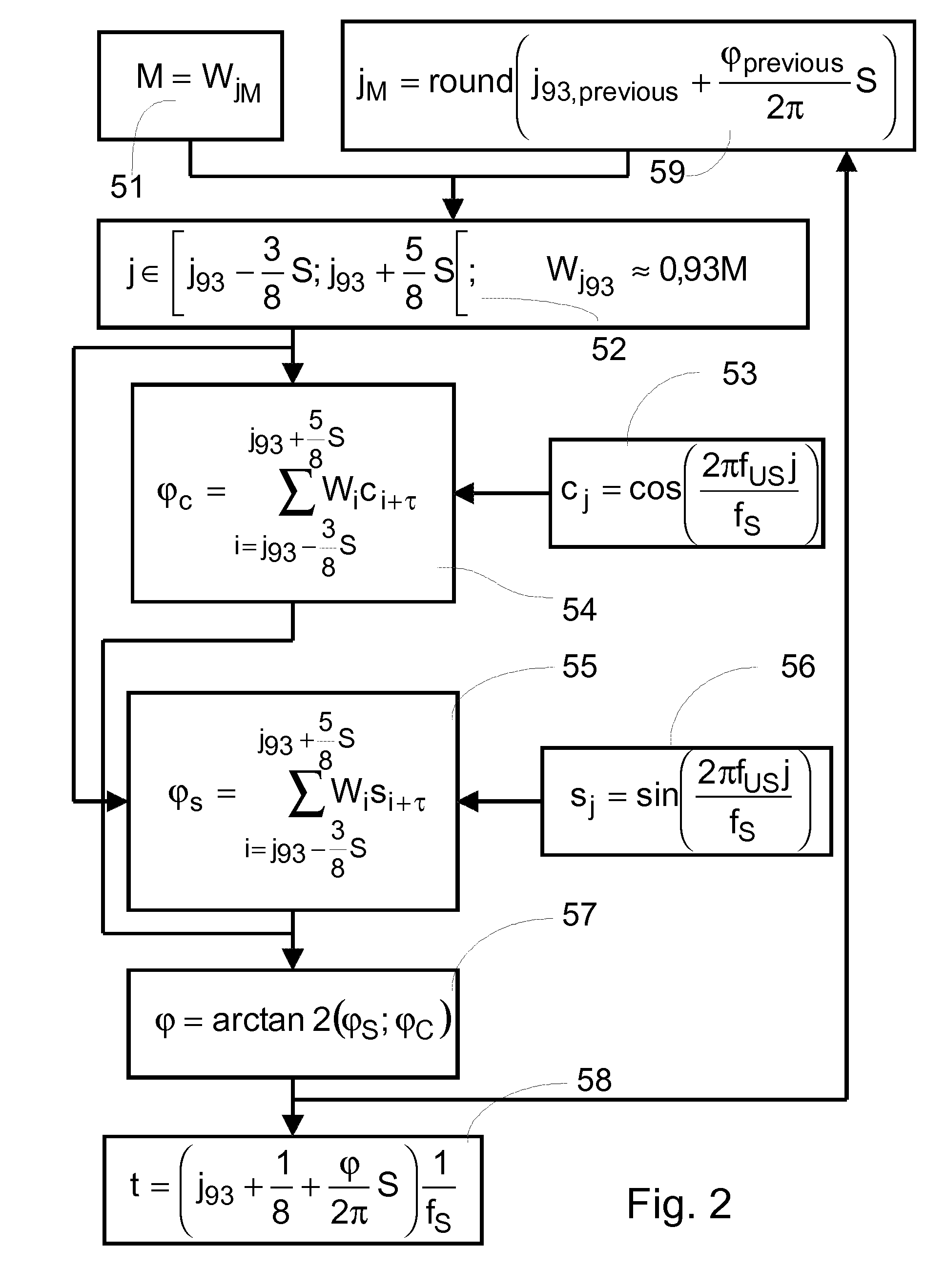
[0061]Thus, there remains the technical problem to measure the propagation time difference Δt or the propagation times t45 and t54 with sufficient exactness. This problem is equivalent to the determination of the temporal position of ultrasound packets, which define, after all, the beginning and the end of Δt. In the embodiments described herein, ultrasonic transducers SC.131.XLV (SECO Se...


PUM


Abstract

The invention relates to a method for determining the temporal position of a wave packet (31) in a flow measuring apparatus, and to a flow measuring apparatus. The method includes the sampling of the wave packet at a plurality of points in time, wherein a measured value is created at each point in time. Subsequently, a sum of products (43, 54, 55, 63, 64) is calculated, wherein each product is calculated for a determined point in time from a plurality of points in time and each product is the product of a value of a compare function (44, 53, 56, 61, 62) at the determined point in time and the measured value at the determined point in time. Finally, the temporal position of the wave packet is calculated from the sum of products.

Description

BACKGROUND OF THE INVENTION[0001]The invention relates to the processing of signals for the exact measurement of a propagation time difference. The invention also relates to flow measuring apparatus, in particular to flow measuring apparatus for detecting the airflow during inspiration and expiration, which utilize the capture effect of ultrasound. Such flow measuring apparatus are also referred to as spirometers.[0002]A number of apparatus are known, which utilize the capture effect of sound waves in fluids, especially air. There are substantially two construction types, which are illustrated in FIGS. 11 and 12.[0003]The flow measuring apparatus 1 illustrated in FIG. 11 comprises a tube 2 as well as a first ultrasonic transducer 4 and a second ultrasonic transducer 5. The tube has a diameter d and an axis 3. Both ultrasonic transducers 4 and 5 are disposed on a second axis 6 so that each of the two transducers picks up the ultrasound generated by the respective other transducer. Th...

Claims


Application Information

Patent Timeline
Patent Type & Authority Patents(United States)
IPC IPC(8): G01F1/66G01F1/7082
CPCA61B5/087G01F1/667G01F1/7082G01S11/14A61B5/726G01F1/712
Inventor GLASER, ECKARDSCHEDER, DANIEL
Owner VYAIRE MEDICAL GMBH
Why Eureka
Try Eureka