
Method for targeting a preferred object within a group of decoys

Active Publication Date: 2012-02-14
LOCKHEED MARTIN CORP
View PDF22 Cites 13 Cited by
  • Summary
  • Abstract
  • Description
  • Claims
  • Application Information

AI Technical Summary

Benefits of technology

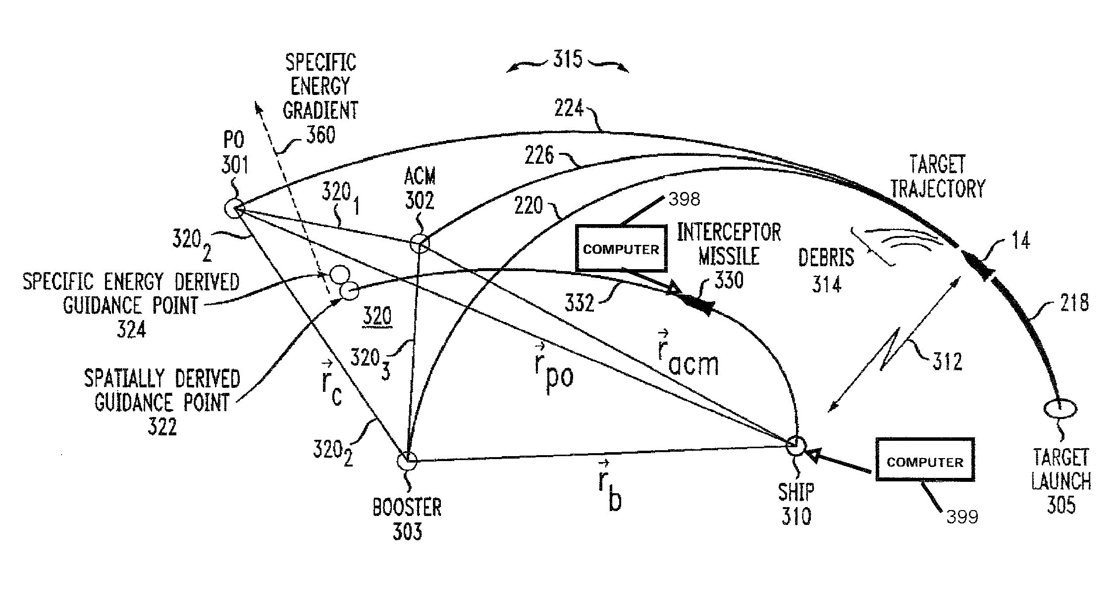
[0006]An engagement system according to an aspect of the invention is for targeting and engaging a preferred object among a group of non-preferred objects. The system comprises at least one sensor (312) for sensing a group of potential target objects (preferred object, acm, B, 315) which includes a preferred object and an associated group of non-preferred objects, to thereby produce position and velocity vectors for each potential target object. The system also comprises a computer arrangement, which may be a single computer or a distributed computer, and which may include modules for performing specific tasks or an integrated software entity for performing multiple specific tasks. The computer includes at least an aspect for computing, from the position and velocity vectors, at least one of specific energy and specific angular momentum for each of the potential target objects, to thereby produce constants of orbital motion. A computer or ranking aspect thereof ranks the constants of orbital motion for each of the potential target objects, and deems the three target objects having values above a threshold (of the one of the specific energy and specific angular momentum) as identifying a group of the three most likely target objects. A computer or spatially derived guidance point aspect thereof calculates the spatially derived guidance point of the group of three most likely target objects, and calculates the spatial rate of change of the constants of orbital motion, to thereby produce a guidance direction increment. A computer or combining aspect thereof combines the spatially derived guidance point with the guidance direction increment, to thereby produce an interceptor vehicle target point which is closer to the location of the preferred object than is the spatially derived guidance point. A controllable thrust controller is coupled to receive the interceptor vehicle target point, and is also coupled to the interceptor vehicle, for controlling the thrust of the interceptor vehicle to guide the interceptor vehicle toward the target point. In a particularly advantageous aspect of the system, a computer or identification aspect thereof is coupled for receiving at least the constants of orbital motion, for determining which of the potential target objects is the preferred object, and for generating a command for a transition from guidance toward the target point to guidance toward the preferred object. A computer or aspect thereof is coupled to the interceptor vehicle and to receive the command for transition from guidance toward the target point to guidance toward the preferred object, and effectuates the transition from guidance toward the target point to guidance toward the preferred object.

Problems solved by technology

Current threats in the art of hostile ballistic missiles include the deployment of decoys to make it difficult to identify the preferred object (the object targeted for intercept).

Method used


Image

  • Method for targeting a preferred object within a group of decoys
  • Method for targeting a preferred object within a group of decoys
  • Method for targeting a preferred object within a group of decoys

Examples


Embodiment Construction

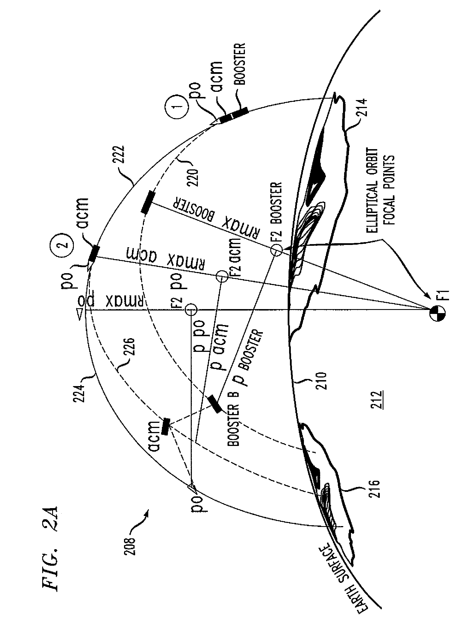
[0015]The “guide” point toward which the interceptor is guided is chosen so as to contain the preferred object (po) within the divert capability of the interceptor. This can be important because the objects of the ballistic group or cluster may diverge at a rate which does not allow all of them to be contained using the prior-art spatially derived guidance point method. It should be noted that the spatially derived guidance point lies in a plane which contains those three objects of a group having specific energy or specific angular momentum above a threshold value. According to an aspect of the invention, the interceptor aim, guide, or target point before terminal guidance begins is shifted or deviated away from the spatially derived guidance point and toward the preferred object. This allows containment of those objects likely to be the preferred object within the interceptor divert capability. The shifting or deviation of the guide or target point is based on orbital parameters o...


PUM


Abstract

Current targeting approaches involve guiding to a spatially derived guidepoint of a group of objects likely to be the preferred object. This method may not allow the intercepting missile to contain the preferred, or other probable object(s), within its divert capability. The guidepoint is shifted closer to the preferred object using specific energy and angular momentum, constants of orbital motion, which describe properties of an object's trajectory. Guiding to the specific energy derived guidepoint does not offer significant benefit over guiding to the spatially derived guidance point. However, computing the spatial rate of change of specific energy within the plane formed by the guidance objects establishes a vector pointing close to the preferred object. This is the direction to shift the guidepoint in order to contain the preferred object within the interceptor's divert capability.

Description

BACKGROUND OF THE INVENTION[0001]Current threats in the art of hostile ballistic missiles include the deployment of decoys to make it difficult to identify the preferred object (the object targeted for intercept). The decoy objects for the most part travel in a ballistic manner along paths similar to those of the preferred object. The deployment method may result in mutual separation of the decoy objects from each other and from the preferred object, possibly with high speed. The decoy objects may include booster housing(s), ejected shrouds, metal-surfaced balloons inflated after reaching ballistic operation, including large balloons enclosing the preferred object, a booster of boosters, an attitude control module (acm) and various other objects. “Busing” is used with some missiles, whereby a single boost vehicle carries multiple preferred objects, in which case each preferred object may be viewed as being a decoy as to the other preferred object.[0002]Defense against ballistic miss...

Claims


Application Information

Patent Timeline
IPC IPC(8): F41G7/30F41G7/00G01S13/00F42B15/00
CPCF41H11/02F41G7/30
Inventor BOARDMAN, JONATHAN ALANPATEL, NARESH RAMANBOKA, JEFFREY BRUCE
Owner LOCKHEED MARTIN CORP
Learn More