Rotary tube notching apparatus

a technology of notching apparatus and rotary tube, which is applied in the direction of turning machine accessories, drilling machines, manufacturing tools, etc., can solve the problems of insufficient room to properly position the elongated tube member, binding and/or damage to the workpiece, and misalignment of the cutting head and pipe, so as to reduce the overall work space required, facilitate assembly and use, and eliminate unwanted movement during operation

Inactive Publication Date: 2009-10-27
HUGHES JR ROBERT K
View PDF38 Cites 13 Cited by
  • Summary
  • Abstract
  • Description
  • Claims
  • Application Information

AI Technical Summary

Benefits of technology

[0013]Still another object of the subject invention is to provide a tube notching apparatus designed to secure and maintain the work object in a substantially horizontal position regardless of the angle of notch being created thereby enabling the device to be located closer to surrounding walls if desired or necessary and reducing the overall work space required to perform notching tasks.
[0014]Yet another object of the subject invention is to provide a tube notching apparatus designed such that all major components are in close proximity to one another and constructed in such manner as to eliminate unwanted movement during operation thereby assuring proper alignment of cutting means and work object.
[0015]It is also an object of the subject invention to provide a tube notching apparatus that is comprised of relatively few components to facilitate easy assembly and use as well as reduce the chances of mechanical failure.
[0016]Another object of the subject invention is to provide a rotary tube notching apparatus which is relatively simple in design and therefore capable of rapid construction at relatively low costs.

Problems solved by technology

A first problem with this arrangement is that there is often insufficient room to properly position elongate tube members since movement is impeded by either the floor (when adjusting the tube about a vertical plane) or by surrounding walls or other table mounted equipment (when adjusting the tube about a horizontal plane).
A second problem frequently encountered is that the weight of the hand drill causes the cutting member to descend too rapidly into the work piece which can result in binding and / or damage to the work piece.
An apparent shortcoming of the Story device, is that the carriage unit which supports the cutter head unit is comprised of two relatively thin and elongated arms which are likely to bend under the weight of an attached hand drill thereby causing misalignment of the cutting head and pipe.
Moreover, tube notching devices of the prior art are neither designed for nor suited to create offset notches in the work piece (i.e., where the center of the hole saw does not intersect the longitudinal axis of the work piece) or to notch curved sections of bent tubing.

Method used


Image

  • Rotary tube notching apparatus
  • Rotary tube notching apparatus
  • Rotary tube notching apparatus

Examples


Embodiment Construction

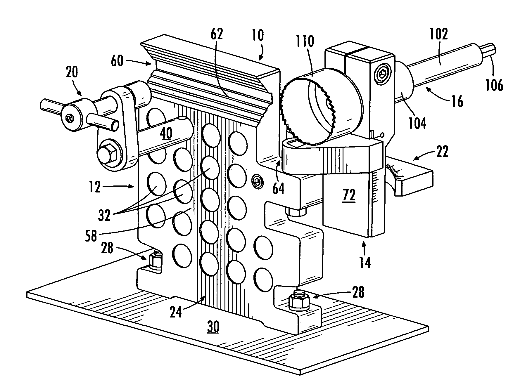
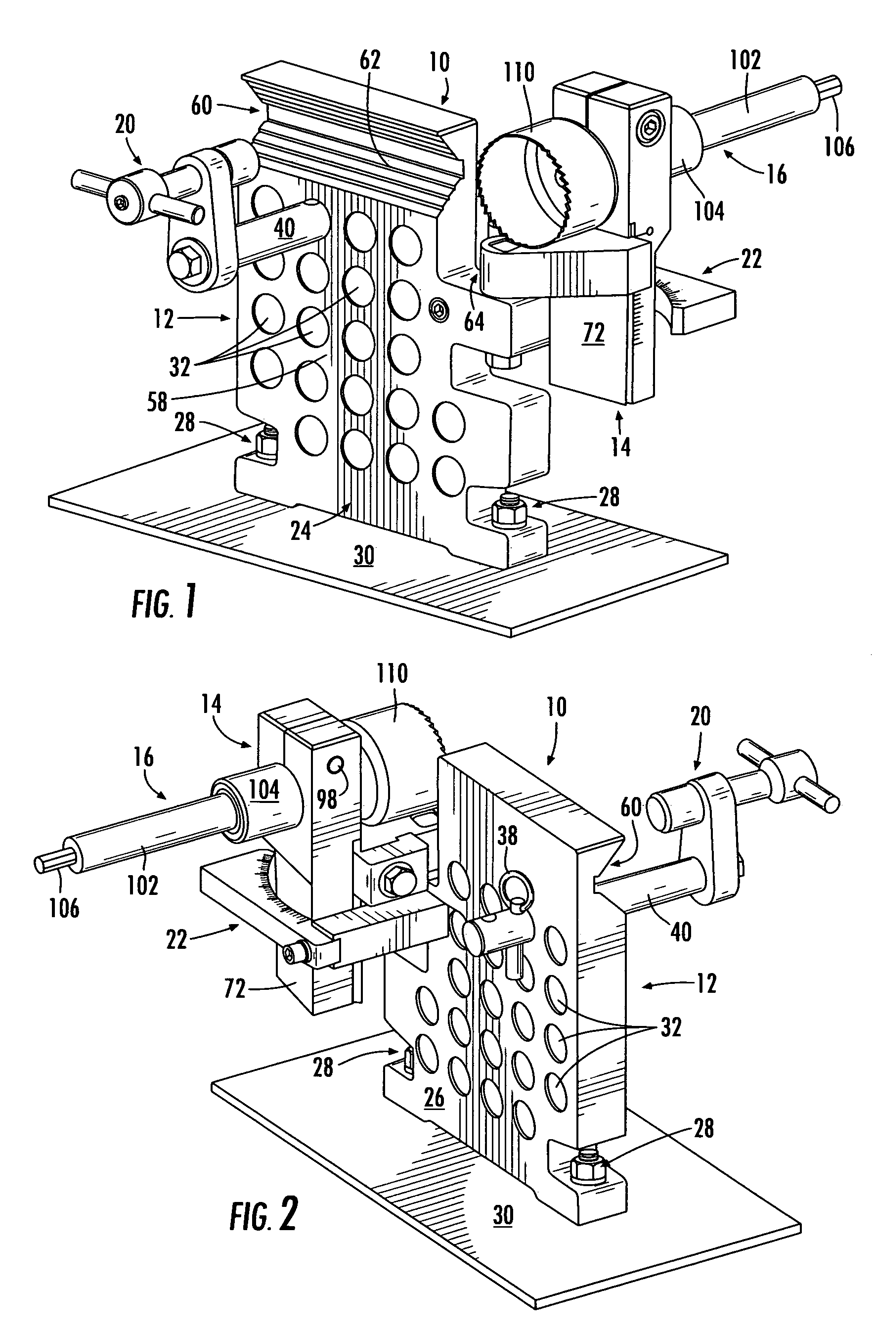
[0030]Reference is now made to FIGS. 1 and 2 in which there is illustrated front and rear views, respectively, of the subject rotary tube notching apparatus (hereinafter sometimes also referred to as simply “notching apparatus” or “tube notcher”), designated generally by reference numeral 10. In its broadest sense, the subject invention is a rotary tube notching apparatus capable of operable attachment to a powered rotational drive device such as a drill, and is comprised of three primary components, namely a surface mountable tube support assembly 12; a height adjustable carriage assembly 14 pivotally mounted to tube support assembly 12, and a shaft assembly 16 rotatably mounted to carriage assembly 14. Each of these components is more fully described below in seriatim, followed by a description of the functionality of the apparatus as a whole.

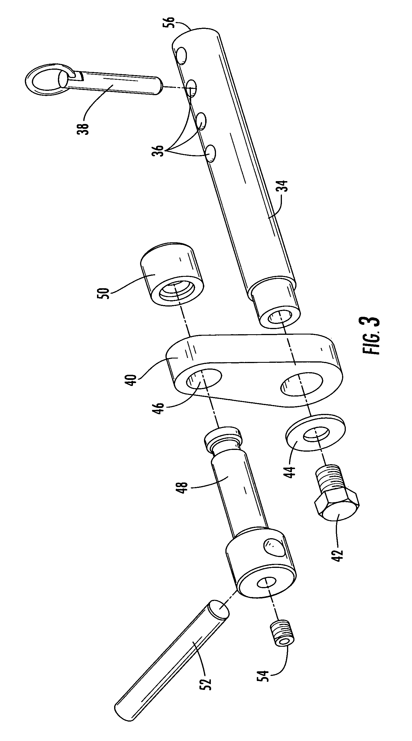
[0031]Tube support assembly 12 is comprised of a vertical frame member 18, tube retention means 20, and angle indicator 22 (described infra)...


PUM

PropertyMeasurementUnit
heightaaaaaaaaaa
degree of rotationaaaaaaaaaa
axis of rotationaaaaaaaaaa

Abstract

A rotary tube notching apparatus capable of operable attachment to a powered rotational drive device such as a drill, is comprised of a surface mountable tube support assembly capable of alternately receiving straight or bent tubing; a height adjustable carriage assembly pivotally mounted to the tube support assembly to enable offset notching, and a shaft assembly rotatably mounted to said carriage assembly for receiving a cutting tool.

Description

FIELD OF THE INVENTION[0001]The subject invention relates to tube notchers generally, and to an adjustable rotary tube notching apparatus capable of performing straight, angled and offset cuts in both straight and bent tubing, in particular.BACKGROUND OF THE INVENTION[0002]In order to manufacture products comprised of tubular metal, such as automotive exhaust systems, roll-cages and numerous other framed support structures, it is necessary to join sections of hollow metal tubing by means of arc welding, electron beam welding, laser welding and brazing or soldering. In order to accomplish proper interconnection of such tubing members for permanent union it is first necessary to “notch” one of the tubes so that it matingly conforms to the exterior surface of the tube to which it is to be connected. Several methods have been employed to achieve the desired fit of such abutting tubular surfaces including the use of hand-held coping tools, punch and die combinations and band saws. The su...

Claims


Application Information

Patent Timeline
Patent Type & Authority Patents(United States)
IPC IPC(8): B23B47/28
CPCB23B41/003B23B47/281B23B2215/72Y10T408/564Y10T408/5612Y10T408/5614Y10T408/563B23B2247/18
Inventor HUGHES, JR., ROBERT K.
Owner HUGHES JR ROBERT K
Why Eureka
Try Eureka