Electromagnetic ultrasonic transducer and array thereof

a transducer and electromagnetic technology, applied in the field of ultrasonic therapy, can solve the problems that the electromagnetic ultrasonic transducer used in ultrasonic examination cannot be applied to ultrasonic therapy directly, the frequency of the electromagnetic ultrasonic transducer used in ultrasonic examination is low, and the type of electromagnetic ultrasonic transducer used in ultrasonic examination cannot be realized. achieve the effect of improving structure, simple manufacturing process and strong power

Active Publication Date: 2012-02-14
RONGHAI SUPERSONIC MEDICINE EN
View PDF5 Cites 11 Cited by
  • Summary
  • Abstract
  • Description
  • Claims
  • Application Information

AI Technical Summary

Benefits of technology

[0006]In prior art, the size of elastic coil or elastic magnet conducting diaphragm is generally of the order of centimeter. The frequency of this kind of ultrasonic transducers is mostly within the range of audio frequency. The smaller the size of elastic coil or elastic magnet conducting diaphragm, the higher the generated frequency of ultrasonic waves, and the maximum generated frequency of ultrasonic waves can reach megahertz level. Therefore, the magnetizer can be made as one of the order of microns in the present invention by use of micromachining technology and accordingly the elastic coil or elastic magnet conducting diaphragm can produce ultrasonic waves with high-frequency.
[0010]More preferably, the winding direction of coils on the support makes the direction of inductive current generated in the elastic magnet conducting diaphragm be vertical to the direction of magnetic field in the soft magnet. At this time, the Lorentz Force generated in the magnet field generator is the maximum and the magnetic attraction to the magnetizer is also the maximum. Under the action of this force, the elastic board can generate the maximum vibration and transmit ultrasound waves with extremely high frequency.
[0011]More preferably, the shape of said support may be a concave one. Two ends of the elastic board are fixed on two protuberant parts at both ends of the support by elastic fixing material. Thus, an air sink is formed at the concave in the middle of the support. The concave soft magnet is easy and convenient to generate the magnetic field parallel to the winding direction of coils and accordingly the maximum Lorentz Force is generated to attract the magnetizer. The air sink formed at the concave in the middle of the concave support is a favorable condition for the elastic unit (referring to the elastic board and the magnetizer on it) to generate vibration and meanwhile, it is a favorable condition for the elastic unit to transmit ultrasonic waves because of small damping but big ultrasonic attenuation of the air sink.
[0012]In the present invention, other shapes, such as C-shape and E-shape may be adopted for the support. But the concave support is the preferable one because it is processed simply and has a low manufacturing cost.
[0021]More preferably, the shape of said support may be a concave one. Two ends of the elastic board are fixed on two protuberant parts at both ends of the support by elastic fixing material. Thus, an air sink is formed at the concave in the middle of the support. The concave soft magnet is easy and convenient to generate the magnetic field parallel to the winding direction of coils and accordingly the maximum Lorentz Force can be generated to attract the magnetizer. The air sink formed at the concave in the middle of the concave support is a favorable condition for the elastic unit to generate vibration and meanwhile, it is also a favorable condition for the elastic unit to transmit ultrasonic waves because of small damping but big ultrasonic attenuation of the air sink. Other shapes, such as C-shape and E-shape may be adopted for the support. But the concave support is the preferable one because it is processed simply and has a low manufacturing cost.
[0024]Because the electromagnetic ultrasonic transducer has its own unique advantages, for example, strong power generated by it and relatively simple manufacturing process, the electromagnetic ultrasonic transducers array of the present invention, as a complete electromagnetic ultrasonic transducer, is formed by a plenty of small electromagnetic ultrasonic transducers of the order of microns, while the complete electromagnetic ultrasonic transducer is not assembled directly with traditional large-sized components. The frequency of the complete electromagnetic ultrasonic transducer is basically determined by the frequency of each small transducer unit. Therefore, this improvement on structure can greatly increase the frequency of the electromagnetic ultrasonic transducer.

Problems solved by technology

But the electromagnetic ultrasonic transducer used in ultrasonic examinations has a low frequency and the focusing is hard to be realized, thus, this kind of electromagnetic ultrasonic transducer for inspections cannot be applied to ultrasonic therapy directly.

Method used


Image

  • Electromagnetic ultrasonic transducer and array thereof
  • Electromagnetic ultrasonic transducer and array thereof
  • Electromagnetic ultrasonic transducer and array thereof

Examples


embodiment 1

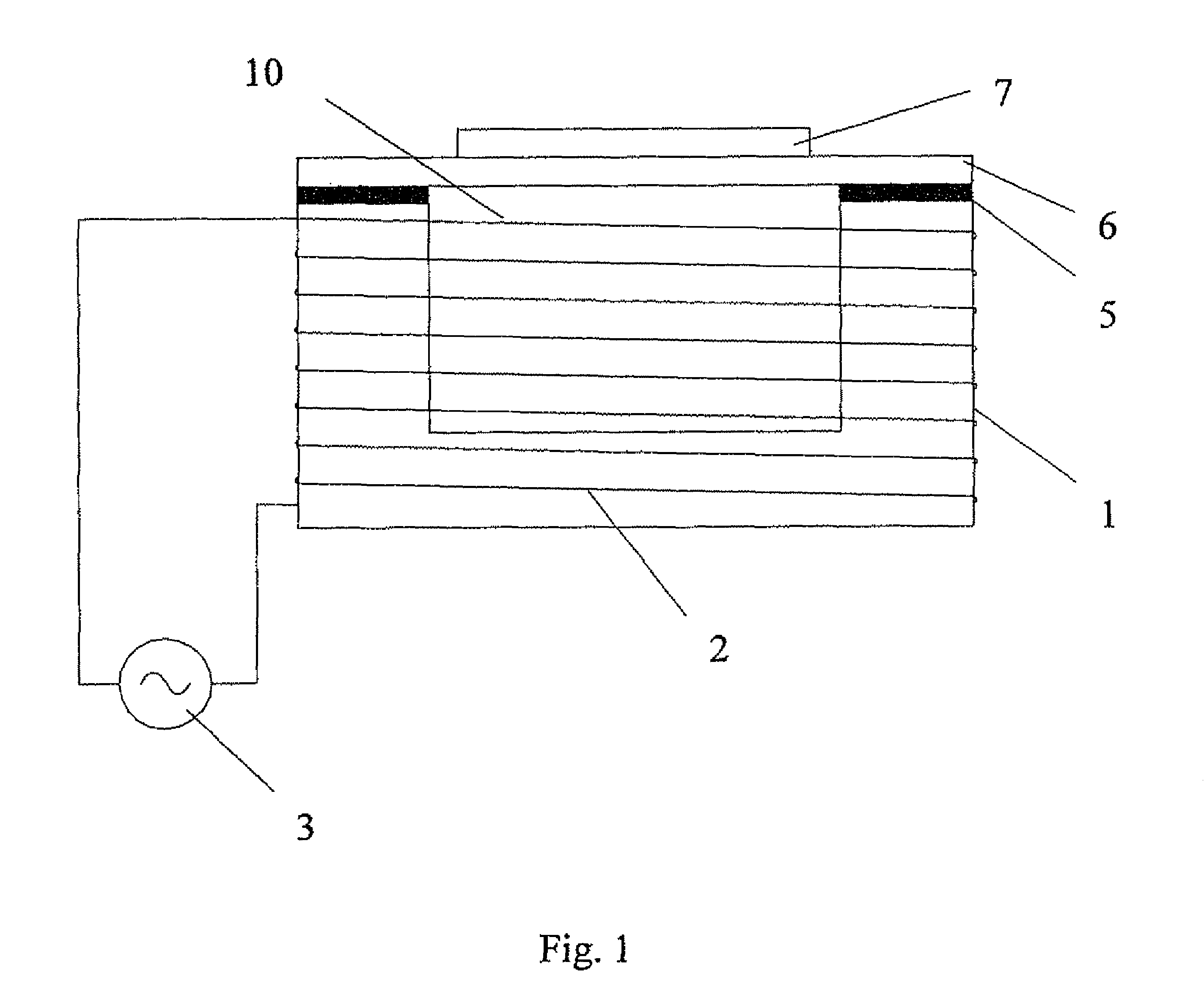
[0042]As shown in FIG. 1, the electromagnetic ultrasonic transducer comprises: an elastic board 6, a magnetizer on the elastic board 6 and a magnet field generator for making the magnetizer vibrate. Wherein, the magnetizer is of the order of microns and it is plated on the elastic board 6. The magnetizer adopts magnet conducting diaphragm 7, for example, nickel, with a thickness ranging from 0.1 to 100 microns. In this embodiment, the magnet field generator comprises: a support 8 made of soft magnet for supporting elastic board 6, coil 2 wound on this soft magnet and A. C. power supply 3 connected to the coil 2.

[0043]In this embodiment, the elastic board 6 also adopts a rectangle-shaped plate of the order of microns with a length ranging from 10 to 300 microns, a width ranging from 10 to 300 microns and a thickness ranging from 5 to 500 microns. Because the elastic board 6 has a high elasticity, good process ability and good mechanical strength, it can be made by the metal material,...

embodiment 2

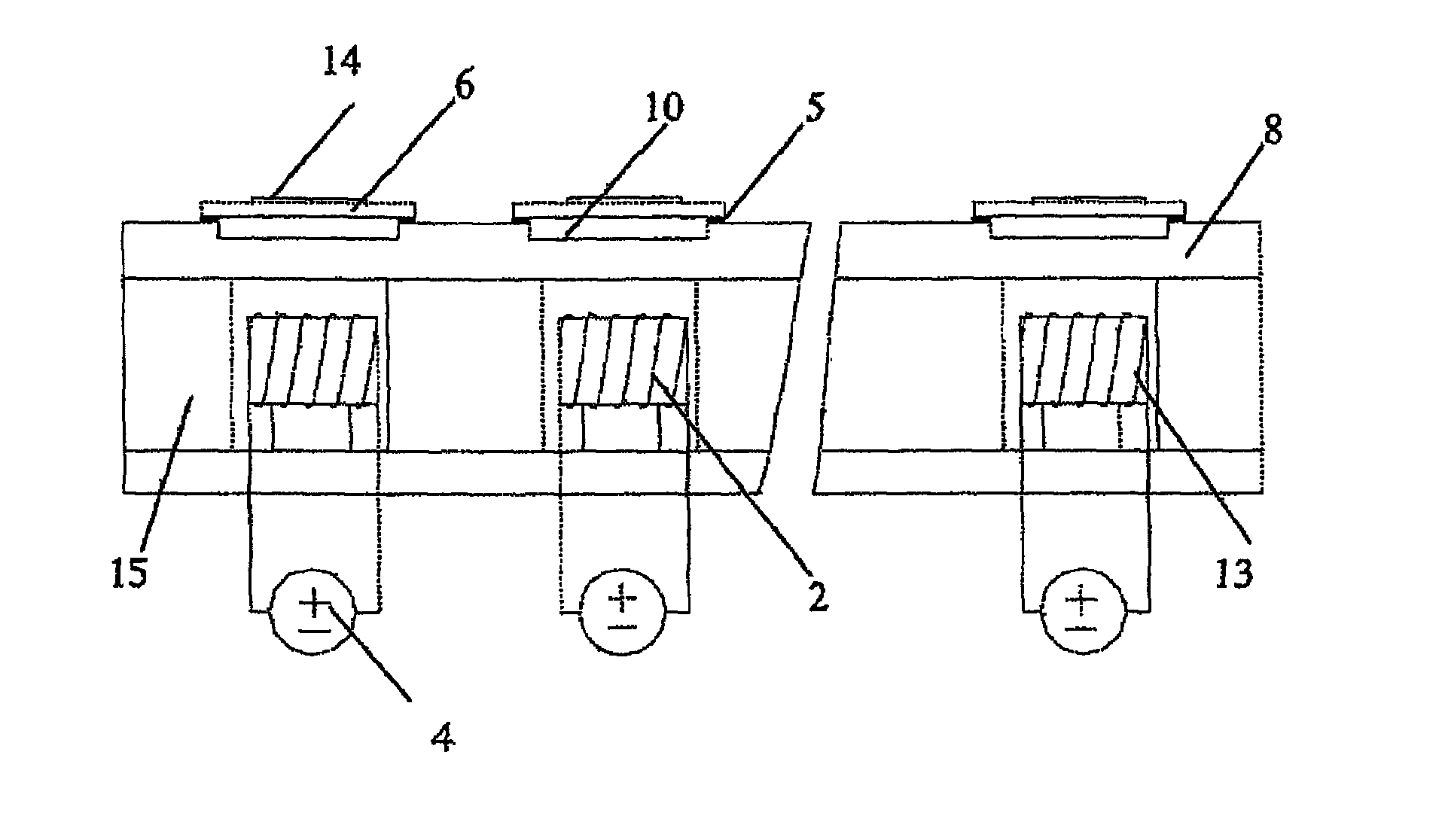
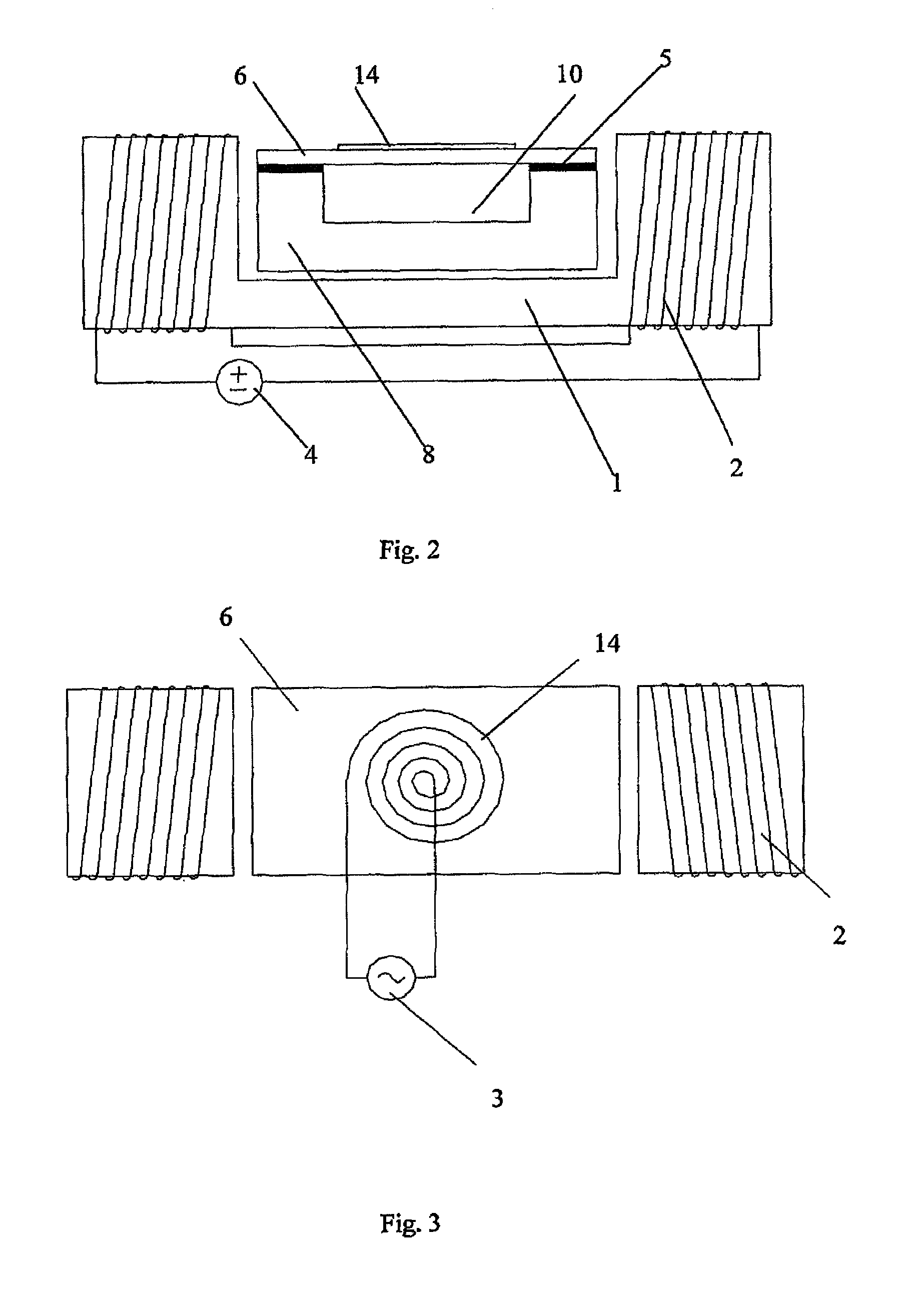
[0049]As shown in FIG. 2 and FIG. 3, the electromagnetic ultrasonic transducer comprises: an elastic board 6 disposed on the support 8, a magnetizer on the elastic board 6 and a magnet field generator for making the magnetizer vibrate.

[0050]Wherein, the magnetizer is of the order of microns. As shown in FIG. 3, the magnetizer is the coil lithographed by micromachining technology (for example, photolithographic way) on the elastic board 6, i.e. the photolithographic coil 14, which is connected to A. C. power supply 3. In this embodiment, the thickness of photolithographic coil 14 ranges from 0.5 to 200 microns.

[0051]The magnet field generator comprises: a concave soft magnet 1, coil 2 wound around two protuberant parts of the concave soft magnet 1 and D. C. power supply 4 connected to the coil 2. Wherein, the support 8 is fixed at the concave in the middle of concave soft magnet 1 and adopts non-magnetizable material.

[0052]The elastic board 6 is rectangle-shaped. In this embodiment, ...

embodiment 3

[0058]As shown in FIG. 4 and FIG. 5, the electromagnetic ultrasonic transducer of this embodiment is different from that in embodiment 2 because their magnet field generators are different. The concave permanent magnet 9 is used in this embodiment to replace the concave soft magnet 1, coil 2 wound around two protuberant parts of the concave soft magnet 1 and D. C. power supply 4 connected to the coil 2 in the embodiment 2.

[0059]Other structures and methods of use in this embodiment are the same as those in the embodiment 2.


PUM


Abstract

An electromagnetic ultrasonic transducer and an array thereof are provided. This electromagnetic ultrasonic transducer includes a support, an elastic board disposed on the support, a magnetizer on the elastic board, and a magnet field generator for vibrating the magnetizer, wherein, the thickness of the magnetizer is of the order of microns. The thickness of the elastic board is also of the order of microns. This electromagnetic ultrasonic transducer is able to produce acoustic waves of high frequency, which are useful for ultrasonic therapy.

Description

FIELD OF THE INVENTION[0001]The present invention pertains to the field of ultrasonic therapy, and relates to ultrasonic transducer for ultrasonic therapy and, particularly to an electromagnetic ultrasonic transducer and an array thereof.BACKGROUND OF THE INVENTION[0002]The electromagnetic ultrasonic transducer is a new type of ultrasonic waves source and it mainly comprises elastic vibration slice, vibrating coil (or magnet conducting vibrating diaphragm) and magnetostatic coil (or permanent magnet). Its working principle is as follows: an electrified coil is affected by Lorentz Force in a magnetic field. When alternating current goes through the coil, the bulk and direction of force on the vibrating coil will vary accordingly. If the vibrating coil is fixed on the elastic vibration slice, the Lorentz Force on the vibrating coil makes the elastic vibration slice vibrate and accordingly the sound waves are transmitted therefrom. The electromagnetic horn is made by use of this princi...

Claims


Application Information

Patent Timeline
Patent Type & Authority Patents(United States)
IPC IPC(8): H04R1/00H04R9/06H04R11/02
CPCA61H23/0245A61N7/00B06B1/04
Inventor WANG, HAIYAN, SIYUANJING, LIMAO, AIHUA
Owner RONGHAI SUPERSONIC MEDICINE EN
Why Eureka
Try Eureka