Working apparatus

a technology of working apparatus and working surface, which is applied in the direction of gear teeth, manufacturing apparatus, gear teeth, etc., can solve the problems of requiring heavy workload and long processing time, affecting the safety and stability of work, and causing unnecessary “burrs” on the outer edge of work, etc., to achieve simple structure, simple surface shape, and safe and stable rotation.

Inactive Publication Date: 2012-02-21
SENJO SEIKI
View PDF8 Cites 6 Cited by
  • Summary
  • Abstract
  • Description
  • Claims
  • Application Information

AI Technical Summary

Benefits of technology

[0013]In the light of problems as discussed above, it is an object of the present invention to provide a working apparatus, which can carry out deburring, chamfering and finishing of work W in complicated shape such as worm gear, of which shape would change not only in cross sectional direction, but also in axial direction, with simple structure, and with precision and effective performance.
[0022]Preferably, according to the working apparatus, the work rotation axis angle adjustment mechanism is provided with: the swing frame for supporting the work hold and rotation means; the swing shaft integrally attached to the swing frame; the slide unit provided with the thread shaft in which the male thread being engraved and also provided with the female thread block for engaging with the thread shaft; and the link mechanism for converting motion of the slide unit in traverse direction into rotative direction of the swing shaft. The swing frame swings by traverse movement of the slide unit via the link mechanism and the swing shaft, whereby angle of rotation axis of the work by the work hold and rotation means may be adjusted. Thus the angle of rotation axis of the work can be adjusted precisely by simple structure.
[0023]Preferably, according to the working apparatus, the link mechanism comprises, the swing arm swinging integrally with the swing shaft, and the link arm for connecting the swing arm and the slide unit. The swing arm has the arc-shaped slotted hole of which circumferential center is positioned at swing fulcrum of the swing arm. Also the lock means is provided, capable of fixing angle of rotation axis of the work by fastening the lock bolt inserted in the slotted hole. Thus the adjusted angle of the work rotation axis can be locked, and the work can be rotated safely and stably.
[0024]Preferably, according to the working apparatus, there is further the working tool rotation axis angle adjustment mechanism, capable of adjusting angle of rotation axis of the working tool. Therefore, both the rotation axis angle of the work, and the rotation axis angle of the working tool, can be adjusted, and thus the deburring, chamfering and finishing of the work having more complicated surface shape can be carried out. In addition, it is also possible to relatively expand the angle of action regarding the working means and the trace means against the work.
[0025]Preferably, according to the working apparatus, the working tool rotation axis angle adjustment mechanism also comprises the rotation forcing means, on which the working means may be mounted in rotative state, and which adjusts angle of rotation axis of the working tool by rotating the working tool. Thus the angle of rotation axis of the working tool can be adjusted precisely by simple structure.
[0026]Preferably, according to the working apparatus, there is the lock means for locking and holding the angle adjusted by the working tool rotation axis angle adjustment mechanism. Thus the adjusted angle of the working tool rotation axis can be locked, and the working tool can be rotated safely and stably.

Problems solved by technology

When the work has been manufactured by any working machine, through cutting work, die casting, injection molding, punching press, lost-wax casting, or die forging, there would occur unnecessary “burr” on the outer edge of the work.
However, such kind of working machine would move the cutting tool based on predetermined trajectory information obtained by a model work, thus the same and stereotypical cutting work would be applied to every work.
This would require heavy workload and long processing time.
However, the working apparatus as disclosed above would have several problems.
Consequently, it is very difficult to carry out chamfering and finishing of the work W, such as the worm gear, by using conventional working machine as discussed above.

Method used


Image

  • Working apparatus
  • Working apparatus
  • Working apparatus

Examples


Embodiment Construction

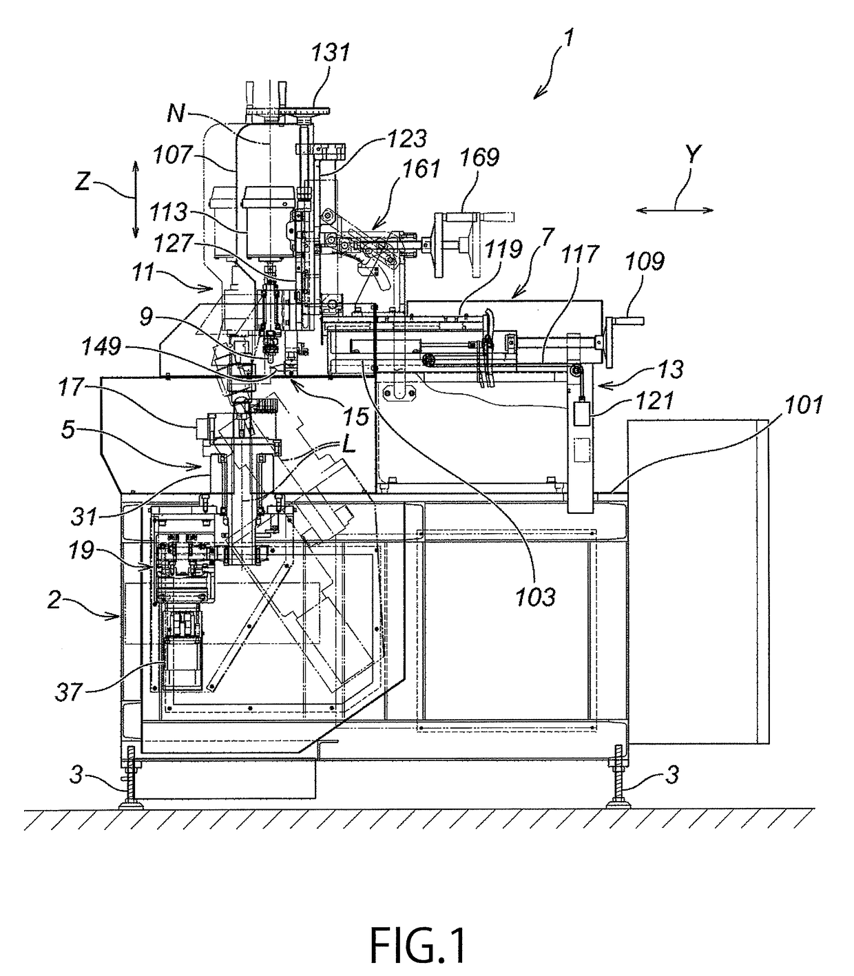
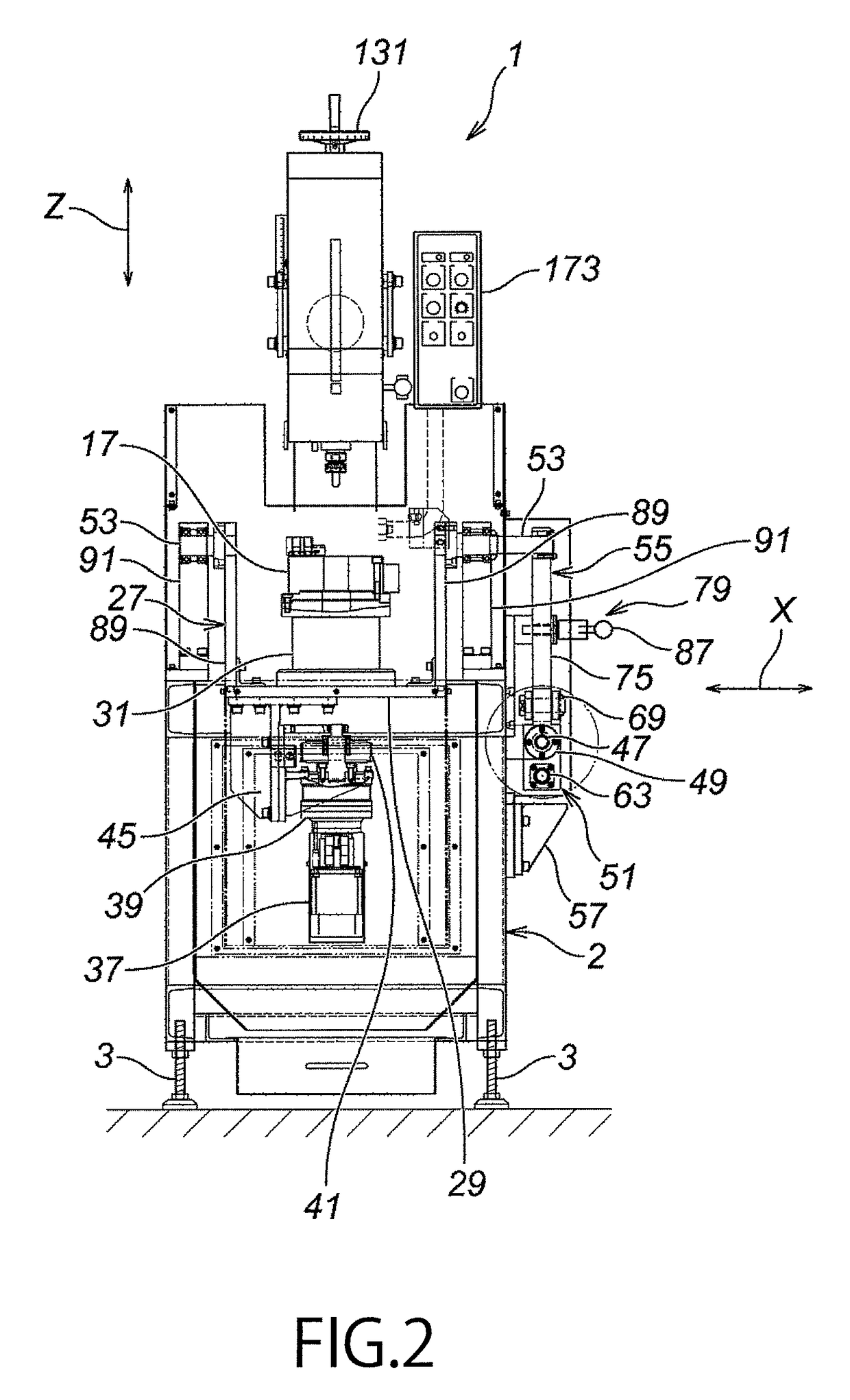
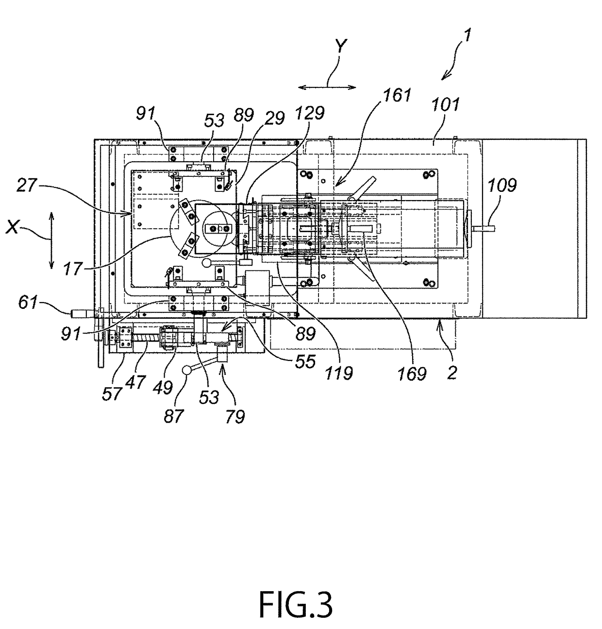
[0044]An embodiment of the present invention will now be described with reference to FIGS. 1 through 15. FIG. 1 is a side view of a working apparatus according to the present invention, serving for various workings such as deburring, chamfering and finishing on the surface of work. FIG. 2 is a front view, and FIG. 3 is a plan view, respectively, of the working apparatus according to the present embodiment.

[0045]There is a working apparatus 1 having a base stage 2. The base stage 2 is made of frame members such as channel steel, assembled to form as rectangular frames. As shown in FIGS. 1 and 2, each corner on the bottom surface of the base stage has a height-adjustable leg 3, thus there are in total four legs 3 (among which, FIGS. 1 and 2 show only two legs 3). There are work hold and rotation means 5, slider mechanism 7, working means 11 and press means 13 mounted on the base stage 2. The work hold and rotation means 5 holds and rotates a work W. The working means 11 is provided on...


PUM

PropertyMeasurementUnit
angleaaaaaaaaaa
angleaaaaaaaaaa
shapeaaaaaaaaaa

Abstract

A working apparatus, provided with a base stage, work hold and rotation device for holding and rotating a work, working device movable toward and away from the work via slider mechanism and having a working tool, press structure for pressing the working tool toward the work via the working device, and trace device pressed toward the work together with the working tool by the press structure and in contact with the work and moving the working device as a whole in forward and rearward directions according to outer shape of the work. By pressing of the pressing structure, the working tool deburrs and chamfers under control of working volume by the trace device. The work hold and rotation device has work rotation axis angle adjustment mechanism, for adjusting angle of rotation axis of the work by holding the work. The working apparatus can precisely deburr and chamfer complicated shape of work such as worm gear.

Description

BACKGROUND OF THE INVENTION[0001]1. Field of the Invention[0002]The present invention relates to a working apparatus. The working apparatus of the present invention is provided with trace means, which traces the outer surface of industrial component having complicated shape such as worm gear, which has been manufactured by any working machine through cutting work, die casting, injection molding, punching press, lost-wax casting, die forging, etc., (hereinafter, such industrial components will be collectively referred to as “work”), so that the trace means may trace the optimum shape of work, for the purpose of deburring or chamfering of such work. The working apparatus of the present invention is also provided with working means for working on the surface of the work, and with work hold and rotation means which rotates the work by keeping the position of the work.[0003]2. Description of the Related Art[0004]When the work has been manufactured by any working machine, through cutting ...

Claims


Application Information

Patent Timeline
Patent Type & Authority Patents(United States)
IPC IPC(8): B23F11/00B23C3/12B23Q16/00B23C1/14B23F23/08B23F19/10
CPCB23C3/12B23F19/10B23Q35/10B24B9/04B23C2220/20Y10T409/304256Y10T409/107473Y10T409/305824Y10T409/304144Y10T409/307672Y10T409/101113Y10T409/10954
Inventor NAKAJIMA, MASAHARU
Owner SENJO SEIKI
Why Eureka
Try Eureka